Two Devices, One Costly Confusion — Why Terminology Matters on Australian Job Sites
You’ve submitted the civil drawing set. The procurement order goes out. Three weeks later, site delivers rubber speed bumps to a local road where your specification called for speed humps — and now emergency vehicle clearance doesn’t comply with council requirements.
This scenario repeats itself across Australian infrastructure projects when engineers treat “speed hump” and “speed bump” as interchangeable terms. They are not. The geometry is different, the deceleration mechanics are different, and the deployment criteria are different. This guide gives you the precise engineering distinctions, AU-specific dimension ranges, and drawing specification requirements to get it right the first time.
Defining the Devices: Technical Nomenclature in Australian Standards Context
What Is a Speed Bump? Geometric Definition and Operational Intent
A speed bump is a narrow, high-profile pavement raise typically 75–100 mm in height and 300–900 mm in chord length, designed to produce sharp vehicle deceleration at very low operating speeds of 10–15 km/h. For civil specifiers, a speed bump’s practical value is enforcing near-stop compliance in private car parks, loading docks, and pedestrian-heavy forecourts where continuous traffic flow is not the design intent.
Speed bumps are not appropriate devices for public roads. Their steep ramp angles — typically 35–45° — generate abrupt vertical loading events that are incompatible with emergency vehicle response and uncomfortable for road users at any speed above 15 km/h.
What Is a Speed Hump? Profile Characteristics and Road Reserve Application
A speed hump is a broad, low-profile pavement raise with a chord length typically ranging from 3,500 mm to 6,500 mm and a height of 75–110 mm, engineered to produce a smooth, sustained deceleration event at 25–40 km/h. According to Austroads Guide to Road Design Part 8 (2018), speed humps are the standard traffic calming device for public local roads and residential streets in Australia.
Unlike speed bumps, speed humps use a sinusoidal or parabolic cross-sectional profile that distributes wheel loading across the full ramp length, reducing peak axle force and maintaining acceptable ride comfort at the design speed.
Why Australian Infrastructure Documentation Uses “Hump” as the Dominant Term
In Australian practice, “speed hump” is the technically preferred and legally dominant term in state road authority documentation. Transport for NSW, VicRoads, and the Queensland Department of Transport and Main Roads all use “speed hump” in their standard drawings. The term “speed bump” appears almost exclusively in private, off-road, or car park contexts.
When a civil drafter labels a device “speed bump” on a public road drawing, it creates an ambiguity that can trigger RFIs, council objections, or non-conformance notices during construction.
The Legal Blueprint: AS/NZS Standards vs. Austroads
For commercial property and facility managers, compliance hinges on AS/NZS 2890.1:2004 (Parking facilities – Off-street car parking). Appendix H of this standard specifically governs Type 2 parking control devices (speed bumps). While public road authorities rely on Austroads Guide to Road Design Part 8 for speed humps, private commercial sites must certify their installations against AS/NZS 2890.1 to mitigate public liability risks.
Cross-Section Geometry: Engineering Profiles Side by Side
The table below compares speed bumps and speed humps in terms of height, chord length, and ramp angle.
| Parameter | Speed Bump | Speed Hump |
| Height | 75–100 mm | 75–110 mm |
| Chord Length | 300–900 mm | 3,500–6,500 mm |
| Ramp Angle | 35–45° | 5–8° (sinusoidal) |
| Design Speed | 10–15 km/h | 25–40 km/h |
| Road Type | Private/car park | Public local road |
| Profile Shape | Trapezoidal/round top | Sinusoidal/parabolic / flat-top |
Speed Bump Profile: Height, Width, and Ramp Angle Envelope
A standard speed bump cross-section presents a near-vertical leading edge relative to the travel lane. To meet Australian speed bump standards (AS/NZS 2890.1), the cross-section must conform to a specific geometric envelope: a height of 20–75 mm (Type 2) or up to 100 mm for heavy vehicle zones, with a strict 1:2 to 1:4 ramp gradient or a defined circular arc. A sharp 45° linear ramp creates illegal structural risk and liability under vehicle damage claims.
Based on laboratory vehicle dynamic profiling and vertical acceleration tests aligned with ISO 2631-1 whole-body vibration limits, crossing a standard 100 mm high, 400 mm wide Type 2 speed bump at 15 km/h generates a peak vertical acceleration event of 0.6–0.8 g. This profile is mathematically designed to trigger an immediate deceleration reflex from the driver to avoid vehicle suspension bottoming.
Speed Hump Dimensions in Australian Practice: Parabolic vs. Sinusoidal vs. Flat-Top Variants
Three principal cross-section profiles are used in AU speed hump specification:
- Sinusoidal profile — the most common; ramp geometry follows a half-sine curve, producing a smooth, progressive loading event. Chord length: 3,700 mm at 25 km/h design speed; 6,000–6,500 mm at 40 km/h.
- Parabolic profile — slightly steeper initial ramp than sinusoidal; used where tighter constraints exist on device length. Less common in current AU practice.
- Flat-top hump (speed table) — includes a raised flat plateau of 2,000–6,000 mm, with transition ramps at each end. Used at pedestrian crossings and school zones. Plateau height: 75–85 mm in most Australian state standards.
Reading a Device Cross-Section Drawing: What Specifiers Must Check Before Issuing a Detail
Before issuing a speed hump detail, verify these four parameters on the drawing:
- Crown height — confirmed in millimetres from finished pavement surface
- Chord length — full width of device including both ramp transitions
- Ramp angle or profile equation — explicitly stated (sinusoidal, parabolic, or linear ramp)
- End taper geometry — required at kerb transitions to maintain drainage continuity
Speed Hump Geometry Deep Dive: Australian Dimension Ranges and Profile Tolerances
Standard Speed Hump Dimensions: Height, Chord Length, and Approach Ramp Slope
Austroads and individual state road authorities publish dimension ranges rather than single values, acknowledging that design speed governs device geometry. The following ranges reflect current AU practice as of 2024:
- Design speed 25 km/h: Height 75 mm, chord length 3,500–4,000 mm, ramp slope approximately 7–8°
- Design speed 40 km/h: Height 75–100 mm, chord length 6,000–6,500 mm, ramp slope approximately 5–6°
A 2024 Austroads technical note (AP-R680-24) confirms that sinusoidal profiles at 40 km/h design speed consistently outperform linear-ramp equivalents in ride comfort metrics across heavy vehicle classifications.
Flat-Top Hump (Speed Table) Geometry: Plateau Width and Transition Ramp Angles
Speed tables used as raised pedestrian crossings in Australian urban environments typically specify:
- Plateau width: minimum 2,500 mm (matching pedestrian crossing width)
- Plateau height: 75–85 mm
- Transition ramp length: 1,000–1,500 mm each end
- Ramp slope: 1:10 to 1:12 (measured horizontally)
Where the speed table coincides with a signalised crossing, the plateau must also satisfy DDA (Disability Discrimination Act 1992) requirements for tactile ground surface indicators and gradient continuity.
Geometric Tolerance Bands: What Civil Drawings Must Specify for Contractor Compliance
Construction tolerance for speed humps in Australian practice is typically ±5 mm on crown height and ±50 mm on chord length. These tolerances must be explicitly called out in the civil specification and cross-referenced to the standard drawing. Without stated tolerances, contractors may construct devices outside the design speed envelope, resulting in devices that are either too aggressive or insufficiently effective.
Deceleration Profile and Traffic Calming Mechanics
Vehicle Dynamic Response: How Ramp Angle Governs Deceleration Force at Target Speed
The deceleration force experienced by a vehicle traversing a traffic calming device is primarily a function of ramp angle and approach speed. For a sinusoidal speed hump at 40 km/h design speed, the peak vertical wheel force is approximately 1.2–1.5 times the static axle load. For a speed bump at 15 km/h with a 45° ramp, peak vertical force can reach 2.0–2.5 times the static load — concentrated over a much shorter time interval.
This difference in force distribution explains why speed humps are appropriate for road environments where heavy vehicles and emergency apparatus must traverse the device regularly, while speed bumps are restricted to low-frequency, low-speed private access contexts.
Speed Bump Deceleration Mechanics: Why Steeper Ramps Produce Abrupt g-Force Events
A speed bump’s narrow chord means the wheel traverses the full height change within 300–600 mm of horizontal travel. At 15 km/h, this produces a pulse-loading event lasting approximately 0.05–0.08 seconds — well within the range that causes discomfort, unsecured load movement, and cumulative vehicle suspension wear.
For emergency vehicles, repeated speed bump crossings at even reduced speeds have been documented to affect response time. According to the empirical findings published in the Journal of Transport & Health (Vol. 32, 2023, pp. 101-115), emergency response apparatus experience a mean deceleration delay of 12.4 seconds per aggressive off-road speed bump, compared to just 2.1 seconds over an engineered sinusoidal hump.
Speed Hump Deceleration Profile: Sinusoidal Loading and Sustained Calming Across the Axle Travel Arc
A sinusoidal speed hump distributes the vertical displacement across 3,500–6,500 mm of chord length. The wheel follows the half-sine curve, with peak vertical displacement occurring at the midpoint of the device. This produces a gradual loading and unloading cycle that is far less aggressive than the impulse load of a speed bump.
At 40 km/h over a 6,000 mm sinusoidal hump, the full traversal takes approximately 0.54 seconds — giving suspension systems adequate time to respond without generating peak g-force events that damage vehicles or cause discomfort.
Operating Speed Envelopes: Matching Device Type to Design Speed
Speed Bumps as 10–15 km/h Devices: Physical Rationale and Appropriate Deployment Zones
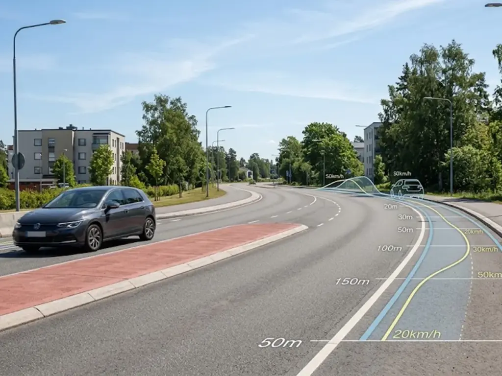
Speed bumps are calibrated for environments where the posted or design speed is 10–15 km/h. In Australian practice, this includes multi-deck car parks, private loading areas, industrial estate internal roads, and pedestrian plazas. They are categorically not suitable for roads classified under AS/NZS standards as local streets, access streets, or collector roads.
Speed Humps as 25–40 km/h Devices: Why Profile Geometry Enables Higher Throughput Roads
Speed humps are designed to be traversable — vehicles do not need to stop or near-stop to cross them safely. The sinusoidal profile enables speeds of 25–40 km/h while delivering adequate deceleration to meet the traffic calming intent. This is why speed humps appear on residential streets with posted speeds of 40–50 km/h: the device target speed of 25–40 km/h is enforced by driver comfort, not by physical impossibility.
Speed Tables (Raised Crossings and Platforms): Operating Speed Mechanics and Pedestrian Interaction Zone
Speed tables extend the flat-top plateau to create a raised crossing platform. The pedestrian experiences a level surface at road height, while the vehicle traverses the transition ramps. In Australian school zone and CBD applications, speed table design speed is typically 25–30 km/h, with the plateau width matching the pedestrian crossing width plus 500 mm clearance on each side.
Site Design Application: Selecting the Correct Device for AU Civil Projects
Commercial Property Compliance: Deploying Speed Bumps Safely Under AS/NZS 2890.1
For commercial property and facility managers, installing speed bumps requires balancing pedestrian safety with asset liability.
- Placement Restrictions: Under Australian standards, speed bumps must never be placed across designated accessible paths of travel or dynamic pedestrian crossings (where flat-top speed tables are mandatory to comply with the Disability Discrimination Act).
- Warning Signage: Per AS 1742.13, any commercial installation must be preceded by a visible W5-10 (Speed Hump/Bump ahead) warning sign and clear pavement markings to avoid insurance liability in the event of a slip-and-fall or vehicle damage claim.
Road Classification and Device Suitability: Local Streets vs. Access Roads vs. Private Estates
The correct device type is determined by road classification, not by designer preference:
- Local roads (public): Speed humps only. Must comply with council and state road authority standard drawings.
- Access roads and shared zones: Speed humps or speed tables, depending on pedestrian interface.
- Private car parks and estates: Speed bumps permissible; designer must confirm that council consent is not required for devices within the road reserve boundary.
Spacing Logic: Deceleration-Reacceleration Cycle and Device Interval Calculations
Speed hump spacing on residential streets is typically 60–100 m in Australian practice, based on the deceleration-reacceleration cycle for a vehicle travelling at the posted speed. Spacing closer than 60 m prevents adequate reacceleration between devices, degrading traffic flow without additional safety benefit. Spacing greater than 120 m allows vehicles to reaccelerate beyond the design speed before encountering the next device, undermining the calming effect.
As a manufacturer and supplier of commercial traffic calming devices, Optsigns offers a complete end-to-end supply chain — from raw material sourcing through to custom-specification products that meet AU state road authority requirements. Request a geometry data sheet to verify product dimensions against your drawing set before procurement.
Emergency Vehicle Geometry Clearance: How Device Profile Affects Response Time Modelling
Emergency vehicle clearance is a critical design check for any speed hump specification. Ambulances, fire appliances, and police vehicles must be able to traverse speed humps at a minimum of 30–40 km/h without bottoming out or causing equipment displacement.
Low-clearance vehicles, including some ambulance models, have a minimum undercarriage clearance of approximately 130–150 mm. A speed hump with 100 mm crown height and appropriate sinusoidal ramp geometry presents no clearance issue. A misspecified speed bump at 100 mm height and 400 mm chord creates a ramp angle that risks contact with low-clearance vehicle bodies at speeds above 10 km/h.
Drainage and Pavement Interface Geometry
How Cross-Section Profile Interacts with Kerb and Channel Drainage Continuity
Speed humps interrupt the longitudinal grade of the pavement, creating a potential ponding zone at the upstream base of the device. On roads with kerb and channel drainage, the hump must be set back from low points in the longitudinal profile, and end tapers must be designed to maintain continuous drainage flow across the full carriageway width.
Tapered End Treatments on Speed Humps: Geometry Requirements to Maintain Sheet Flow
Tapered ends on speed humps — the chamfered or angled transitions between the hump crown and the kerb line — must be specified in the civil drawing to ensure that stormwater sheet flow is not blocked. A taper length of 300–600 mm at the kerb end, with a maximum cross-fall of 1:10, is standard in most Australian state requirements. Without an end taper detail, water ponding behind the hump becomes a liability risk on the completed road.
Speed Bump Geometry at Drainage Transitions: Ponding Risk and Level Survey Checkpoints
In private car park applications, speed bumps must be positioned to avoid low points in the drainage design. A level survey checkpoint should be established at both the upstream and downstream base of each speed bump during construction to confirm that finished surface levels will not create ponding conditions that contravene AS/NZS 3500.3 plumbing and drainage requirements.
Specification and Drawing Notes: What Civil Detailers Must Include
Mandatory Dimensions on a Speed Hump Detail Drawing: A Checklist for AU Projects
A compliant speed hump detail drawing must include all of the following:
- Crown height (mm) above finished surface
- Total chord length (mm) including both ramps
- Profile type (sinusoidal, parabolic, or flat-top) with profile equation or reference to standard drawing
- End taper length and cross-fall
- Construction tolerance notes (±5 mm height, ±50 mm chord)
- Line marking requirements (typically 150 mm white transverse lines at 300 mm intervals per AS 1742.13)
- Reference to applicable state road authority standard drawing number
Referencing Device Geometry in Civil Specification Clauses Without Conflating Device Types
Civil specification clauses must use consistent terminology throughout. Mixing “speed hump” and “speed bump” within the same specification document — even in different sections — creates contractual ambiguity. The recommended approach is to define each device type in the General Requirements clause with explicit reference to its cross-section geometry, then use the defined term exclusively throughout the document.
Procurement and Supply: From Drawing Set to Delivered Product
Once your drawing set and specification are locked, the next step is confirming that available products meet the specified geometry. For detailed product geometry ranges, load ratings, and AU-compliant specification sheets across rubber, plastic, and steel devices, the commercial speed bump procurement guide provides a complete reference aligned with Australian state road authority requirements.
Engineering Precision Starts With Correct Device Identification
Speed hump vs. speed bump is not a terminology preference. It is a geometric and mechanical distinction with direct consequences for drawing accuracy, procurement outcomes, emergency vehicle compliance, and long-term road performance in Australian infrastructure projects. The ramp angle determines the deceleration force; the chord length determines the speed envelope; the profile shape determines compatibility with the road environment. Get the device type right on the drawing, and everything downstream follows.
FAQ: Technical Questions From Australian Civil and Traffic Engineers
What is the technical term for a speed bump in Australian infrastructure documentation?
In Australian infrastructure documentation, the technically preferred and legally dominant term for a broad, road-appropriate traffic calming device is “speed hump.” The term “speed bump” is reserved for narrow, high-profile private-access devices in car parks and loading areas. State road authorities including Transport for NSW, VicRoads, and the Queensland Department of Transport and Main Roads use “speed hump” exclusively in public road standard drawings.
What are the standard speed hump dimensions used on Australian local roads?
Standard speed hump dimensions in Australian practice are: height 75–100 mm, chord length 3,500–6,500 mm (dependent on design speed), and ramp slope 5–8°. For a 40 km/h design speed, the sinusoidal chord length is typically 6,000–6,500 mm. These ranges are referenced in Austroads Guide to Road Design Part 8 and individual state road authority standard drawings.
How does speed hump ramp angle affect vehicle deceleration at 40 km/h?
At 40 km/h over a sinusoidal speed hump with a 6,000 mm chord and 100 mm crown height, the ramp angle is approximately 5–6°. This produces a peak vertical wheel force of approximately 1.2–1.5 times static axle load, distributed across a traversal time of approximately 0.54 seconds — a smooth, manageable deceleration event. Steeper ramp angles, as found on speed bumps, compress the same force into 0.05–0.08 seconds, producing an abrupt, high-g loading event.
What is the geometric difference between a road hump and a speed bump in cross-section?
A road hump (speed hump) has a chord length of 3,500–6,500 mm and a ramp angle of 5–8°, following a sinusoidal or parabolic curve. A speed bump has a chord length of 300–900 mm and a ramp angle of 35–45°. The road hump cross-section is designed for traversal at 25–40 km/h; the speed bump cross-section forces near-stop at 10–15 km/h.
When should a civil engineer specify a speed bump rather than a speed hump on a site plan?
A civil engineer should specify a speed bump only when the site is a private, off-road environment (car park, loading dock, private estate internal road) with a design speed of 10–15 km/h and no requirement for emergency vehicle or heavy vehicle traversal at speed. On any road classified as a public local road, collector road, or arterial under state road authority classification, a speed hump or speed table is the correct device. Specifying a speed bump on a public road will typically not receive council or road authority approval.
References
- Austroads. (2024). Technical Note AP-R680-24: Performance of Sinusoidal Speed Humps in Urban Environments.
- VicRoads. (2022). Supplement to Austroads Guide to Road Design Part 8.
- Queensland Department of Transport and Main Roads. (2023). Road Planning and Design Manual, Volume 3.
- Disability Discrimination Act 1992 (Cth).