योजना पत्रक में कहा गया है 90 डिग्री. चौराहा है 68. आपका दल पहले से ही साइट पर है, लेन बंदी लाइव है, ब्लेड अनपैक्ड हैं - और इंस्टॉलर के हाथ में दो-चेहरे वाला ब्रैकेट भौतिक रूप से दोनों दृष्टिकोणों को दोनों चेहरों को प्रस्तुत नहीं कर सकता है. हर घंटे जब वह असेंबली अनसुलझी रहती है तो क्रू का समय बर्बाद हो जाता है, एक अनुमत समापन का विस्तार करता है, और एक पंच-सूची आइटम को उस कार्य पर धकेलता है जिस पर आपने अपने दिमाग में हस्ताक्षर किया था. ज़्यादा बुरा, एक ब्लेड लगा हुआ 22 इसके एप्रोच अक्ष से कुछ डिग्री दूर आने वाले ड्राइवरों को बढ़त मिलती है, जो बिल्कुल दृष्टि रेखा की विफलता है जिसे आपका निरीक्षक चिह्नित करेगा और आपकी एजेंसी इसकी मालिक होगी.
यह मार्गदर्शिका अनुमान को दोहराने योग्य कॉन्फ़िगरेशन तर्क से बदल देती है. यह दिखाता है कि वास्तविक प्रतिच्छेदन ज्यामिति - क्रॉस को कैसे परिवर्तित किया जाए, टी, विषम, बहु पैर, राउंडअबाउट - रक्षात्मक में सड़क का नाम चिह्न ब्रैकेट कॉन्फ़िगरेशन इससे पहले कि आपका दल सक्रिय हो जाए.
क्यों इंटरसेक्शन ज्योमेट्री - हार्डवेयर प्राथमिकता नहीं - ब्रैकेट कॉन्फ़िगरेशन को निर्देशित करती है
सड़क का नाम चिह्न ब्रैकेट कॉन्फ़िगरेशन एकल बढ़ते नोड के चारों ओर ब्लेड चेहरों की स्थानिक व्यवस्था है, हार्डवेयर कैटलॉग प्राथमिकता के बजाय सड़क मार्ग ज्यामिति द्वारा निर्धारित किया जाता है. एक प्रोजेक्ट इंजीनियर के लिए, व्यावहारिक मूल्य सरल है: ज्योमेट्री को कागज पर सही ढंग से लिख लें और फील्ड इंस्टालेशन एक सुधार के बजाय एक टॉर्क-एंड-वेरिफाई अभ्यास बन जाता है.
नोड-एंड-लेग मॉडल: ऑर्डर देने से पहले एक इंटरसेक्शन को एक्सिस आरेख के रूप में पढ़ना
प्रत्येक चौराहे को एक माउंटिंग नोड प्लस एन एप्रोच लेग के रूप में मानें. तीन चर पूरी तरह से कॉन्फ़िगरेशन का निर्धारण करते हैं:
- पैरों की गिनती - कितने सड़क मार्ग नोड पर मिलते हैं.
- आंतरिक कोण - आसन्न पैरों के बीच मापा गया असर.
- विशिष्ट नाम - कितने अद्वितीय सड़क नाम प्रदर्शित किए जाने चाहिए.
पैर की गिनती ब्लेड की गिनती नहीं है. एक चार-पैर वाला क्रॉस जहां से एक सड़क लगातार गुजरती है, वहां दो ब्लेड की आवश्यकता होती है, चार नहीं. इस संपूर्ण मार्गदर्शिका में मैं शॉर्टहैंड का उपयोग करूंगा: 4एल-90 (चार पैर वाला ऑर्थोगोनल), 3एल-टी (टी जंक्शन), 4एल-एसके (चार पैर तिरछा), 5एल+ (बहु पैर).
जहां सिविल ड्राइंग खराब हो जाती है: प्लान-शीट कोण बनाम. यथा-निर्मित बियरिंग्स
एएएसएचटीओ ग्रीन बुक अनुशंसा करती है कि सड़कें समकोण पर या उसके निकट प्रतिच्छेद करती हैं और नीचे के कोणों के विरुद्ध सलाह देती है 60 डिग्री - जो आपको बताती है कि निर्मित वातावरण का कितना हिस्सा 60-से-90-डिग्री ग्रे ज़ोन में कहीं बैठता है. योजना-दर-क्षेत्र बहाव विरासती राइट-ऑफ़-वे संरेखण से आता है, वक्र-से-स्पर्शरेखा संक्रमण, उपयोगिता संघर्ष जो पोस्ट स्थानांतरण को मजबूर करता है, और कोने की त्रिज्या को पुनः वर्गीकृत किया गया.
पीडीएफ प्लान शीट से एक कोण स्केल करना कोई असर नहीं है. अंगूठे का नियम: किसी भी नोड पर फ़ील्ड-सत्यापन दृष्टिकोण बीयरिंग जहां योजना सेट सबसे हालिया पुनरुत्थान या चौड़ीकरण से पहले होता है.
अनुमान लगाने की लागत: कैसे एक गलत क्लॉक ब्लेड पूरे क्रू कॉलबैक को ट्रिगर करता है
गलत ब्रैकेट कोई भौतिक घटना नहीं है - यह एक श्रम घटना है. एक गलत घड़ी वाला ब्लेड आम तौर पर दूसरी गतिशीलता का उपभोग करता है, दूसरा बाल्टी-ट्रक चक्र, पुनः जारी लेन बंद करने या फ़्लैगिंग सेटअप, और दोबारा निरीक्षण दौरा. 40-नोड गलियारे के पार, ए 10% अपवाद दर जिसे आप डिज़ाइन में पकड़ने में विफल रहे, वह चार अलग-अलग कॉलबैक ईवेंट बन जाती है. ब्रैकेट स्वयं उस क्रम में सबसे सस्ता लाइन आइटम है.
अक्ष तर्क: मैपिंग ब्लेड गिनती, मुख दिशा, और प्रत्येक दृष्टिकोण के लिए ब्रैकेट प्रकार
एकल-अक्ष परिनियोजन: जब एक-तरफ़ा स्ट्रीट नाम ब्रैकेट नोड को पूरी तरह से संतुष्ट करता है
जब भी नोड में केवल एक सार्थक रीडिंग अक्ष होता है तो 1-वे स्ट्रीट नाम ब्रैकेट सही होता है: प्रदर्शित करने के लिए एक ही नाम, एक प्रमुख दृष्टिकोण दिशा, या दूसरा चेहरा जो अवरुद्ध या अनावश्यक होगा. पैरों को समाप्त करना, मध्य-ब्लॉक स्थापनाएँ, गलियों, और एक तरफ़ा युगल पैर सभी यहाँ गिरते हैं.
इसका एक रणनीतिक उपयोग भी है: एक पोस्ट पर खड़ी दो स्वतंत्र रूप से क्लॉक की गई सिंगल-फेस असेंबलियाँ पूर्ण कोणीय स्वतंत्रता प्रदान करती हैं जिसकी कोई निश्चित इकाई तुलना नहीं कर सकती - तिरछी ज्यामिति के लिए प्राथमिक उपकरण, नीचे विस्तार किया गया.
लंबवत युग्म: दो-ब्लेड कॉन्फ़िगरेशन और निश्चित 90-डिग्री अनुमान
90 डिग्री का स्ट्रीट साइन ब्रैकेट आपको दो चेहरों के बीच एक लॉक किए गए ऑर्थोगोनल रिश्ते के लिए प्रतिबद्ध करता है. एक सच्चे 4एल-90 क्रॉसिंग पर, यह आदर्श है - एक पोस्ट, दो ब्लेड, दोनों दृष्टिकोणों के लिए स्वच्छ प्रस्तुति, एक रखरखाव स्पर्श बिंदु.
बाधा अक्षम्य है: असेंबली तिरछापन अवशोषित नहीं कर सकती. क्षेत्र विचलन की प्रत्येक डिग्री सीधे ब्लेड मिसलिग्न्मेंट में स्थानांतरित हो जाती है, क्योंकि हार्डवेयर के पास स्वतंत्रता की कोई घूर्णी डिग्री नहीं है.
हाई-लेग-काउंट नोड्स के लिए थ्री-फेस और क्रॉस-सेपरेटर व्यवस्था
जब तीन या अधिक विशिष्ट नाम एक साथ आते हैं तो तीसरा चेहरा आवश्यक हो जाता है, या जब एक नोड थ्रू स्ट्रीट और विकर्ण दोनों पर काम करता है. एक क्रॉस सेपरेटर साइन ब्रैकेट एक साझा माउंटिंग बिंदु पर ब्लेड-टू-ब्लेड अंतर बनाए रखता है, जहां चेहरे प्रतिच्छेद करते हैं वहां घूर्णी हस्तक्षेप और ब्लेड संपर्क को रोकना.
रिटर्न तेजी से कम हो जाता है. एक ही नोड पर पिछले तीन चेहरे, ब्लेड स्वयं-छाया देने लगते हैं और कोणीय भीड़ से सुपाठ्यता कम हो जाती है. अगर आपको करीब से देखने की जरूरत है दो-चेहरा और तीन-चेहरा असेंबलियाँ भार पथ और ब्लेड क्षमता में कैसे भिन्न होती हैं, वह तुलना अपने स्वयं के मार्गदर्शक में शामिल है.
नीचे दी गई तालिका कोणीय लचीलेपन में तीन कॉन्फ़िगरेशन परिवारों की तुलना करती है, नोड क्षमता, और संरेखण जोखिम.
| विन्यास | कोणीय लचीलापन | प्रति नोड चेहरे | सर्वोत्तम टोपोलॉजी | प्राथमिक संरेखण जोखिम |
| एकल चेहरा (1-रास्ता) | भरा हुआ, प्रति यूनिट | 1 | 3एल-टी तने, दोहे, मृत अंत | दूसरे दृष्टिकोण का अल्प-कवरेज |
| दो-चेहरे को ठीक किया गया (90°) | कोई नहीं | 2 | 4एल-90 ऑर्थोगोनल क्रॉसिंग | तिरछा सीधे ब्लेड पर स्थानांतरित हो गया |
| त्रिमुखी + सेपरेटर | सीमित | 3 | 5एल+ नोड्स, थ्रू-प्लस-विकर्ण | स्वयं छाया, घूर्णी रेंगना |
| स्टैक्ड सिंगल-फेस जोड़ी | भरा हुआ, स्वतंत्र | 2 | 4एल-एसके तिरछा क्रॉसिंग | पवन साइकिलिंग के तहत क्लॉकिंग ड्रिफ्ट |
अनावश्यक ब्लेड बनाए बिना मानक फोर-लेग क्रॉस इंटरसेक्शन को कॉन्फ़िगर करना
चतुर्थांश चयन: अभी तक सही, लगभग सही, और विकर्ण प्लेसमेंट तर्क
चौराहे पर सड़क चिन्ह लगाने का एमयूटीसीडी का उद्देश्य यह है कि ब्लेड निर्णय के बिंदु पर दिखाई दें, ड्राइवर द्वारा मोड़ के लिए प्रतिबद्ध होने के बाद नहीं. दूर-दाएं-कोने पर माउंटिंग दृष्टिकोण पर जल्द से जल्द पहचान प्रदान करता है; निकट-दाईं ओर स्टॉप बार पर पुष्टिकरण के रूप में कार्य करता है.
एक विकर्ण-विपरीत दो-पोस्ट रणनीति सभी चार दृष्टिकोणों को कवर करती है, जबकि प्रति नोड फेस काउंट को दो पर रखती है - अक्सर सबसे कम जोखिम सड़क का नाम चिह्न ब्रैकेट कॉन्फ़िगरेशन एक मानक शहरी ग्रिड के लिए.
एकल-पोस्ट समेकन बनाम. दो-पोस्ट वितरण
पाँच मानदंडों का उपयोग करके निर्णय लें: दृष्टिकोण गति, एप्रोच लेन गिनती, कोने की दृष्टि-त्रिकोण बाधाएँ, सिग्नल मस्तूल हथियारों या उपयोगिता खंभों की उपस्थिति, और प्रति चतुर्थांश में मार्ग का अधिकार उपलब्ध है.
कम गति वाले ग्रिड चौराहे एकल-पोस्ट समेकन को अच्छी तरह से सहन करते हैं. धमनी क्रॉसिंग पर 45 मील प्रति घंटे पहुँचता है, दो पदों पर वितरित करें - समेकन आउटेज जोखिम को केंद्रित करता है, इसलिए एक एकल नॉकडाउन नोड पर सभी तरह की खोज को हटा देता है.
ब्लेड ओरिएंटेशन कन्वेंशन: प्रत्येक नाम को उसके द्वारा पहचानी जाने वाली सड़क के समानांतर स्थापित करना
यह कन्वेन्शन इंस्टालर अक्सर उलटा होता है. सड़क पार करते समय ड्राइवरों द्वारा एक ब्लेड पढ़ा जाता है, इसलिए इसे उस सड़क के समानांतर स्थापित किया गया है जिसे यह नाम दिया गया है.
फ़ील्ड सत्यापन: स्टॉप बार पर एप्रोच लेन में खड़े रहें. ब्लेड का मुख आपकी यात्रा रेखा के वर्गाकार होना चाहिए. यह एक जाँच अधिकांश का समाधान कर देती है “संकेत पीछे की ओर देखते हैं” पंच-सूची आइटम.
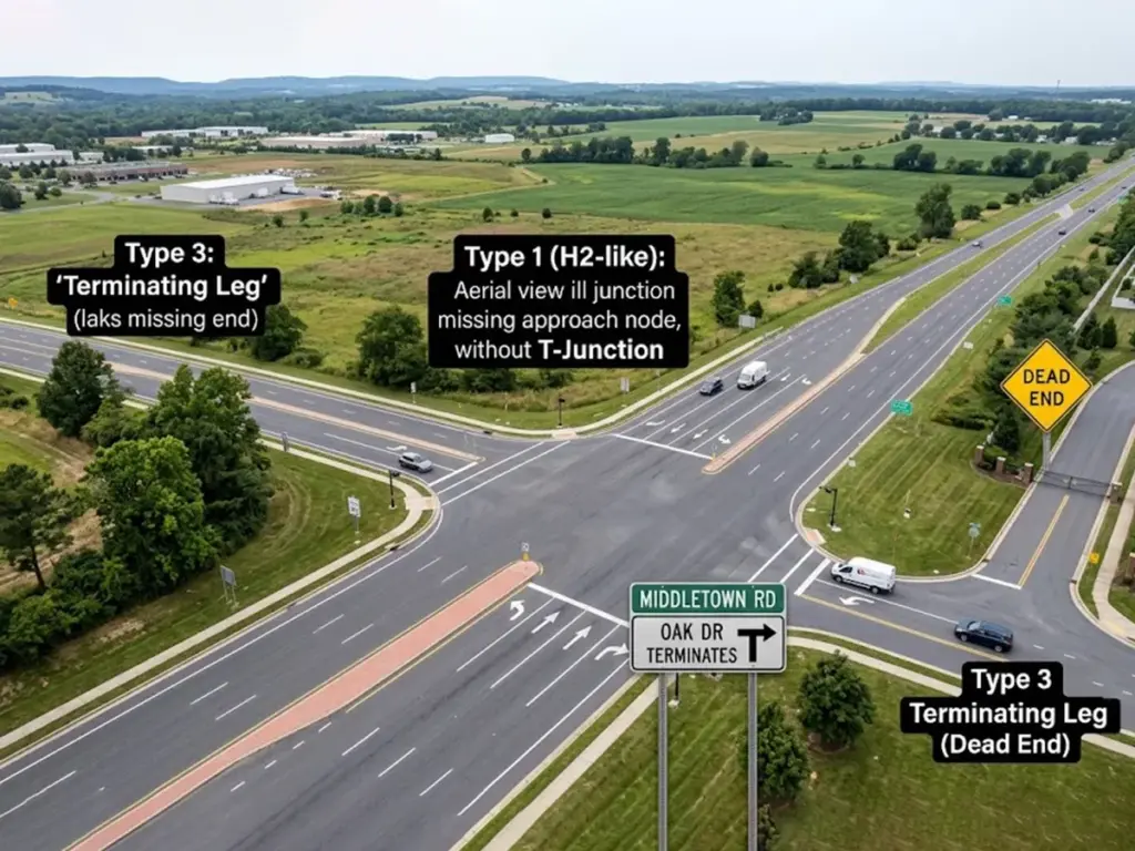
टी जंक्शनों, वाई-विभाजन, और समाप्ति पैर: गुम दृष्टिकोण के साथ नोड्स को कॉन्फ़िगर करना
स्टेम-दृष्टिकोण प्राथमिकता: ड्राइवर के लिए कॉन्फिगर करना, जिसे एक दिशा चुननी होगी
3L-T पर, स्टेम दृष्टिकोण उच्चतम सूचना मांग रखता है - ड्राइवर को बाएं या दाएं का चयन करना होगा - इसलिए स्टेम दृष्टि रेखाएं चेहरे के अभिविन्यास को नियंत्रित करती हैं. मानक संकल्प: स्टेम-एप्रोच ड्राइवरों के लिए थ्रू स्ट्रीट के समानांतर एक ब्लेड, साथ ही आंदोलन के माध्यम से सेवा करने वाला दूसरा चेहरा. सड़क के सुदूर किनारे पर माउंट, निर्णय बिंदु पर ब्लेड को चालक की दृष्टि के शंकु के अंदर रखना.
वाई-स्प्लिट्स और एक्यूट-एंगल पैर: आंतरिक कोण को द्विभाजित करना
जहां आंतरिक कोण काफी नीचे पड़ते हैं 90 डिग्री, दो ओर्थोगोनली माउंटेड ब्लेड, दोनों ही देखने के कोण पर मौजूद हैं - एक दोहरी विफलता. दो सुधार: असेंबली को आंतरिक कोण को समद्विभाजित करने के लिए उन्मुख करें ताकि प्रत्येक चेहरा अंतर को विभाजित कर दे, या प्रत्येक विभाजित पैर पर स्वतंत्र नोड्स पर अलग ब्लेड.
वाई-स्प्लिट्स अक्सर किसी भी निश्चित मल्टी-फेस यूनिट की तुलना में दो सिंगल-फेस असेंबली द्वारा बेहतर ढंग से परोसे जाते हैं.
कल-डी-थैलियों, गलियों, और निजी ड्राइव समाप्ति
इन नोड्स में एक रीडिंग एक्सिस और कम एप्रोच स्पीड होती है. एक ब्लेड सभी ज्यामिति का समर्थन करता है. यहां अति-विशिष्टता सामान्य और महंगी है: मल्टी-फेस हार्डवेयर स्थापित किया गया है जहां सिंगल-फेस स्ट्रीट नेम ब्रैकेट है
पूरा काम करता है.
200-नोड नगरपालिका टेकऑफ़ पर, टर्मिनेशन नोड्स को सही ढंग से डाउनग्रेड करने से अक्सर ऑर्डर से 15-25% मल्टी-फेस हार्डवेयर ट्रिम हो जाता है.
तिरछे और गैर-ऑर्थोगोनल अंतर्संबंधों को हल करना जहां 90-डिग्री ब्रैकेट विफल हो जाते हैं
क्षेत्र में तिरछा परिमाण निर्धारित करना और कार्यशील सहनशीलता निर्धारित करना
प्रत्येक केंद्र रेखा पर दिशा सूचक यंत्र से मापें, एक जीआईएस केंद्ररेखा अज़ीमुथ, या मौजूदा सर्वेक्षण नियंत्रण के लिए कुल-स्टेशन टाई. फिर एक प्रोजेक्ट टॉलरेंस बैंड सेट करें: तिरछी सीमा जिसके भीतर एक निश्चित 90-डिग्री असेंबली अभी भी स्वीकार्य रूप से पढ़ती है, बनाम वह सीमा जहां रोटेशन अनिवार्य हो जाता है.
खरीद के साइन शेड्यूल पर मापी गई बियरिंग्स को रिकॉर्ड करें, इंस्टालेशन, और तीन अलग-अलग धारणाओं के बजाय एक ही संख्या से सभी कार्यों का निरीक्षण करें.
स्वतंत्र क्लॉकिंग: एडजस्टेबल विकल्प के रूप में स्टैक्ड सिंगल-फेस असेंबलीज़
मूल तकनीक: एक सामान्य पोस्ट पर एक निश्चित दो-फेस इकाई को दो स्वतंत्र रूप से घूमने योग्य सिंगल-फेस असेंबली से बदलें, प्रत्येक अपने स्वयं के दृष्टिकोण को ध्यान में रखता है.
ट्रेड-ऑफ़ वास्तविक हैं - लंबवत लिफाफा जोड़ा गया, अधिक फास्टनरों, दूसरा संरेखण चरण. बदले में, आपको पूर्ण कोणीय स्वतंत्रता मिलती है. गवाह चिह्नों के साथ लॉक रोटेशन, एक रिकॉर्ड किया गया क्लॉकिंग संदर्भ, और एक निर्दिष्ट टॉर्क अनुक्रम, या ब्लेड पवन चक्र के तहत स्थानांतरित हो जाएगा.
एक पूरी तरह से एकीकृत ट्रैफिक साइन निर्माता रनिंग सब्सट्रेट के रूप में, कनवास, छपाई, और ब्रैकेट का निर्माण घर में ही किया जाता है, हम आपके रिकॉर्ड किए गए बीयरिंगों के लिए पूर्व-क्लॉक किए गए मिलान वाले ब्लेड-और-ब्रैकेट सेट की आपूर्ति कर सकते हैं - जो अपवाद नोड्स पर फ़ील्ड संरेखण चरण को पूरी तरह से हटा देता है.
ग्लैंसिंग-एंगल ब्लेड प्रेजेंटेशन द्वारा बनाए गए ब्लाइंड स्पॉट को खत्म करना
अनसुलझा तिरछा एक पूर्ण-चेहरे वाले ब्लेड को निकट-किनारे वाले लक्ष्य में परिवर्तित कर देता है, प्रभावी पठनीयता दूरी का पतन. साइन सुपाठ्यता आमतौर पर मोटे तौर पर डिज़ाइन की जाती है 40 प्रति इंच अक्षर की ऊंचाई के अनुसार सुपाठ्य दूरी के फ़ुट - तो 6 इंच के अपरकेस सड़क नाम के बारे में पता चलता है 240 आदर्श के तहत पैर, चौकोर स्थितियाँ. उस ब्लेड को किनारे और उसके उपयोग योग्य हिस्से की ओर घुमाएँ 240 पैर सटीक रूप से सिकुड़ते हैं जब दृष्टिकोण की गति कम से कम प्रतिक्रिया समय छोड़ती है.
फिर द्वितीयक अवरोध जाँच चलाएँ: सिग्नल प्रमुख, मस्त हथियार, सड़क के पेड़, और पारगमन आश्रय जो दृष्टि रेखा को केवल तिरछे कोणों पर क्लिप करते हैं.
लंबवत स्टैकिंग, निकासी, और लोड करें: मल्टी-ब्लेड असेंबलियों का निर्माण जो संरेखित रहें
MUTCD माउंटिंग हाइट और क्लीयरेंस लिफाफे के अंदर काम करना
MUTCD साइन के नीचे न्यूनतम माउंटिंग ऊंचाई निर्धारित करता है 7 व्यापार में पैर, व्यावसायिक, और आवासीय क्षेत्र जहां पार्किंग या पैदल यात्रियों की आवाजाही होती है, और 5 ग्रामीण जिलों में पैर. पार्श्व ऑफसेट सम्मेलन मोटे तौर पर चलते हैं 2 अंकुश वाले खंडों में अंकुश के सामने से पैर और 6 कंधे के किनारे से पैर जहां कोई अंकुश मौजूद नहीं है.
एक मल्टी-ब्लेड स्टैक उस लिफ़ाफ़े को नीचे से ऊपर तक उपभोग करता है. ब्लेडों के बीच जानबूझकर ऊर्ध्वाधर पृथक्करण को सुरक्षित रखें ताकि चेहरे दूरी पर दृष्टिगत रूप से विलीन न हों - और वर्तमान MUTCD संस्करण और आपकी एजेंसी के मानक चित्रों के विरुद्ध मूल्यों की पुष्टि करें, जो अक्सर सख्त होते हैं.
कैंटिलीवर मोमेंट और विंड साइकलिंग: ऑफसेट ब्लेड संरेखण से बाहर क्यों खिसकते हैं?
घूर्णी भार पोस्ट सेंटरलाइन से मोमेंट आर्म द्वारा गुणा किए गए ब्लेड क्षेत्र में उत्पन्न होता है, किसी भी विषमता द्वारा बढ़ाया गया. कॉन्फ़िगरेशन में रेंगने की सबसे अधिक संभावना होती है: एक चेहरे पर लंबे एकल ब्लेड, असंतुलित दोतरफा व्यवस्था, और छोटे-व्यास वाले खंभों पर ऊंचे ढेर.
तीन ज्यामितीय प्रतिक्रियाएँ - चेहरों पर ब्लेड क्षेत्र को संतुलित करें, क्षण भुजा को छोटा करें, और विभाजकों को एक क्लैंप बिंदु के माध्यम से इसे रूट करने के बजाय ब्लेड के बीच लोड वितरित करने दें. स्ट्रक्चरल सपोर्ट डिज़ाइन हाईवे साइन संरचनाओं और एएससीई के लिए एएएसएचटीओ के एलआरएफडी विनिर्देशों का पालन करता है 7 पवन प्रावधान.
पोस्ट साझा करना: विनियामक और चेतावनी संकेतों के साथ सड़क के नाम ब्लेड का समन्वय
विनियामक प्लेसमेंट उस स्थान को बाधित करता है जहां नाम ब्लेड उतरता है, उलटा नहीं. स्टैकिंग ऑर्डर को अंतिम रूप देने से पहले मैप बियरिंग्स, इसलिए रुकें, एक तरफ़ा रास्ता, या टर्न-प्रतिबंध चिह्न पहले से ही उस अक्ष पर नहीं है जिसकी आपके ब्लेड को आवश्यकता है.
शेड्यूल पर पूरी पोस्ट असेंबली का दस्तावेजीकरण करें. कर्मचारियों को अंतिम बढ़ते कदम पर किसी टकराव का सामना नहीं करना चाहिए. प्रत्येक असेंबली प्रकार के लिए सही ब्लेड-माउंट शैली का मिलान
उसी दस्तावेज़ीकरण अभ्यास का हिस्सा है.
मल्टी पैर, दोहा, और राउंडअबाउट नोड्स: जटिल टोपोलॉजी के लिए कॉन्फ़िगरेशन पैटर्न
पाँच- और सिक्स-लेग नोड्स: एक पोस्ट को ओवरलोड करने के बजाय चेहरे वितरित करना
हाई-फेस-काउंट एकल असेंबली कोणीय भीड़ के कारण 5L+ नोड्स पर विफल हो जाती है, ब्लेड हस्तक्षेप, और आत्म-छाया. इसके बजाय वितरित करें: प्रत्येक नाम को उस चतुर्थांश में निर्दिष्ट करें जहां उसका पठन अक्ष सबसे मजबूत हो.
कवरेज ऑडिट: एक दृष्टिकोण-बनाम-नाम मैट्रिक्स बनाएं और पुष्टि करें कि प्रत्येक कोशिका कम से कम एक ब्लेड से संतुष्ट है. दृष्टिकोण दर दृष्टिकोण सत्यापित करें, कभी भी डाक से पोस्ट न करें.
एकतरफ़ा दोहे और युग्मित धमनियाँ: एकल-दिशा दृष्टिकोण के लिए कॉन्फ़िगर करना
एक-तरफ़ा ऑपरेशन संपूर्ण पठन अक्षों को समाप्त कर देता है, आवश्यक चेहरों को काटना - सिंगल-फेस हार्डवेयर के लिए सबसे मजबूत प्राकृतिक मामला. जोड़ी को एक प्रणाली के रूप में सुपाठ्य रखें ताकि ड्राइवर दो समानांतर पैरों में अंतर कर सकें, और उसी पोस्ट पर पहले से ही प्रतिबद्ध दिशात्मक हस्ताक्षर के साथ नाम ब्लेड का समन्वय करें.
गोलचक्कर दृष्टिकोण और परिसंचरण पैर
समस्या को दो भागों में विभाजित करें: प्रवेश से पहले दृष्टिकोण-पैर की पहचान, और परिसंचरण सड़क के भीतर से निकास-पैर की पहचान. रेडियल ज्यामिति लगभग कभी भी प्रयोग करने योग्य 90-डिग्री संबंध उत्पन्न नहीं करती है, जो अधिकांश गोलचक्कर को धक्का देता है सड़क का नाम चिह्न ब्रैकेट कॉन्फ़िगरेशन स्वतंत्र रूप से क्लॉक की गई सिंगल-फेस असेंबलियों की ओर. स्प्लिटर-द्वीप और केंद्रीय-द्वीप बाधाएँ उपलब्ध पोस्ट स्थानों को और सीमित कर देती हैं.
इंटरसेक्शन सर्वे से सत्यापित इंस्टालेशन तक: एक रक्षात्मक ब्रैकेट शेड्यूल का निर्माण
इन्हें पकड़ो 6 आपके ऑर्डर देने से पहले प्रत्येक नोड पर फ़ील्ड
- आने वाले पैरों को गिनें.
- प्रत्येक दृष्टिकोण केंद्र रेखा के असर को मापें.
- प्रदर्शन की आवश्यकता वाले विशिष्ट सड़क नामों की सूची बनाएं.
- प्रति पैर पोस्ट की गई दृष्टिकोण गति रिकॉर्ड करें.
- दृष्टि त्रिकोण के अंदर कोने की रुकावटों पर ध्यान दें.
- मौजूदा पोस्टों और माउंटेड असेंबलियों की सूची.
अपवाद नोड्स को यहां चिह्नित करें - बेस पैकेज के साथ गैर-मानक हार्डवेयर ऑर्डर करें, त्वरित ऐड-ऑन के रूप में कभी नहीं.
थोक खरीद के लिए सर्वेक्षण को प्रति-नोड ब्रैकेट शेड्यूल में परिवर्तित करना
शेड्यूल की संरचना इस प्रकार करें: नोड आईडी, टोपोलॉजी वर्ग (4एल-90 / 3एल-टी / 4एल-एसके / 5एल+), चेहरे की गिनती, प्रति चेहरे ब्लेड ओरिएंटेशन, हार्डवेयर कॉल-आउट. पूरे गलियारे में एक समान कॉन्फ़िगरेशन का आदेश देने के बजाय तिरछे और बहु-पैर वाले नोड्स के लिए एक अपवाद भत्ता बनाएं.
हमें अपना पूरा नोड शेड्यूल भेजें निःशुल्क कॉन्फ़िगरेशन समीक्षा के लिए थोक आरएफक्यू फॉर्म के माध्यम से - हम किसी भी चीज़ के उत्पादन में प्रवेश करने से पहले आपकी प्रतिच्छेदन सूची के विरुद्ध चेहरे की गिनती और अभिविन्यास को क्रॉस-चेक करते हैं.
इंस्टॉल के बाद सत्यापन: ड्राइव-थ्रू साइटलाइन जांच और संरेखण साइन-ऑफ
दो चरणीय QA चलाएँ. स्थिर: ऊंचाई, पार्श्व ऑफसेट, रिकॉर्ड किए गए बियरिंग के विरुद्ध क्लॉकिंग, बांधनेवाला पदार्थ टोक़. गतिशील: प्रत्येक दृष्टिकोण को निर्धारित गति से चलाएं और पुष्टि करें कि ब्लेड स्टॉप बार से काफी पहले वर्गाकार है.
रखरखाव रिकॉर्ड में निर्मित बीयरिंग और अंतिम ब्लेड ओरिएंटेशन के रूप में दस्तावेज़ ताकि अगले दल को इसे फिर से मापने के बजाय ज्यामिति विरासत में मिले. ध्यान दें कि MUTCD 11वां संस्करण जनवरी से प्रभावी हुआ 18, 2024, राज्यों को अपनाने के लिए दो साल का समय दिया गया है - इसलिए शेड्यूल लॉक करने से पहले सत्यापित करें कि आपकी एजेंसी ने अपने मानक चित्र स्थानांतरित कर लिए हैं.
इंटरसेक्शन टोपोलॉजी एक बड़े निर्णय की एक परत है. पूरी तस्वीर के लिए, हमारा देखें साइन माउंटिंग हार्डवेयर परिवारों का पूर्ण विवरण और प्रत्येक कहां से संबंधित है- इस गाइड में प्रत्येक कॉन्फ़िगरेशन निर्णय के लिए मूल संदर्भ.
इंटरसेक्शन माउंटिंग प्रश्न इंजीनियर सबसे अधिक पूछते हैं
मैं एक ही चौराहे पर एक 2-वे ब्रैकेट और दो अलग-अलग 1-वे ब्रैकेट के बीच कैसे निर्णय करूं??
एक निश्चित दो-चेहरे वाली असेंबली का उपयोग केवल तभी करें जब दृष्टिकोण वास्तविक ऑर्थोगोनल कोण पर मिलते हों. एक बार मापे जाने पर तिरछापन आपके प्रोजेक्ट की सहनशीलता से अधिक हो जाता है, दो स्वतंत्र रूप से क्लॉक की गई सिंगल-फेस असेंबलियों पर स्विच करें, चूँकि केवल स्वतंत्र घूर्णन ही कोणीय अंतर को अवशोषित करता है.
90 डिग्री का स्ट्रीट साइन ब्रैकेट किस तिरछे कोण पर काम करना बंद कर देता है?
कोई सार्वभौमिक कटऑफ नहीं है - यह दृष्टिकोण गति और आवश्यक सुपाठ्यता दूरी के साथ मापता है, क्योंकि तेज़ दृष्टिकोण बहुत कम कोणीय त्रुटि को सहन करते हैं. सर्वेक्षण के दौरान एक परियोजना-विशिष्ट सहिष्णुता निर्धारित करें और इसके अलावा किसी भी चीज़ को अपवाद नोड के रूप में मानें.
चार-पैर वाले चौराहे के किस कोने पर सड़क नाम सभा चलनी चाहिए?
दूर-दाएँ-कोने का स्थान आने वाले ड्राइवरों को जल्द से जल्द पहचान देता है; निकट-दाईं ओर स्टॉप बार पर पुष्टि के रूप में कार्य करता है. कई एजेंसियां बिना डुप्लिकेट ब्लेड के सभी चार दृष्टिकोणों को कवर करने के लिए तिरछे विपरीत पोस्ट का उपयोग करती हैं.
क्या सड़क के नाम का ब्लेड उस सड़क के समानांतर या लंबवत लगाया जाना चाहिए जिसे वह नाम देता है?
जिस सड़क का नाम है उसके समानांतर. सड़क पार करने वाले ड्राइवर इसे पढ़ते हैं, इसलिए एक समानांतर माउंट उस ट्रैफ़िक के लिए एक वर्गाकार चेहरा प्रस्तुत करता है जिसे वास्तव में जानकारी की आवश्यकता होती है.
सुपाठ्यता प्रभावित होने से पहले मैं एक पोस्ट पर कितने ब्लेड रख सकता हूं?
सीमा बढ़ते ऊंचाई लिफ़ाफ़े और आवश्यक ऊर्ध्वाधर पृथक्करण द्वारा निर्धारित की जाती है, ब्रैकेट नहीं. एक बार जब सबसे निचला ब्लेड 7 फुट की शहरी निकासी के करीब पहुंच जाता है या ब्लेड एक-दूसरे को छाया देना शुरू कर देते हैं, अतिरिक्त चतुर्थांशों में नाम वितरित करें.
संदर्भ
एफएचडब्ल्यूए - MUTCD 11वां संस्करण अंतिम नियम / प्रभावी तिथि और गोद लेने की खिड़की
AASHTO — राजमार्गों और सड़कों के ज्यामितीय डिजाइन पर एक नीति (हरी किताब), प्रतिच्छेदन कोण मार्गदर्शन
एएससीई 7 - इमारतों और अन्य संरचनाओं के लिए न्यूनतम डिज़ाइन भार और संबद्ध मानदंड (पवन प्रावधान)
एफएचडब्ल्यूए - राउंडअबाउट्स सूचनात्मक मार्गदर्शिका (दृष्टिकोण और परिसंचरण हस्ताक्षर)