Die Perimeter-Sicherheitsinfrastruktur bietet nur dann Schutz, wenn ihre Verankerung Bestand hat. Wenn ein Fahrzeug gegen eine Sicherheitsbarriere prallt, die kinetische Energie verlagert sich vollständig in die Erdverbindung. Die Wahl zwischen einem eingebetteten Fundament und einem oberflächenmontierten System bestimmt, ob die Barriere fest steht oder beim Aufprall abschert.
Daten des Storefront Safety Council zeigen, dass es im Laufe der Zeit zu Zusammenstößen mit Fahrzeugen in Gebäuden kommt 60 Mal pro Tag in den Vereinigten Staaten, was zu mehr als führt 4,000 jährliche Verletzungen (Quelle: https://www.storefrontsafety.org/crash-statistics). Für Facility Manager vor Ort, Eine ordnungsgemäße Konstruktion der Bodenschnittstelle verhindert katastrophale Gebäudeschäden und schützt Fußgängerzonen vor strukturellem Versagen.
Bewertung der Pollerfundamenttypen: Strukturelle Stabilität und Projektumfang
Direktbestattung vs. Oberflächenmontage: Kernprofile für Sicherheit und Schlagfestigkeit
Bei der direkten Erdverlegung kommt es auf eine tiefe Einkapselung des Bodens an. Die umgebende Betonmasse überträgt Aufprallkräfte direkt in die Erde, Minimierung der lokalen Scherbeanspruchung des Pfostens selbst. Oberflächenmontageinstallationen basieren auf der Zugfestigkeit von Stahlankern und der Druckkapazität einer bereits vorhandenen Platte. Eine oberflächenmontierte Barriere bewältigt Stöße mit geringerer Geschwindigkeit, wohingegen ein eingebettetes System kinetische Hochenergieübertragungen überlebt.
Navigieren durch Site-Einschränkungen: Bodenintegrität, Vorhandene Platten, und Ausgrabungsgrenzen
Die bestehenden Anlagenbedingungen schränken die Installationswege ein. Für die Einrichtung eines Direktbestattungssystems sind Kernbohrungen erforderlich, tiefe Ausgrabung, und Bodenbewertung. Sofern der Standort ungestört ist, bindiger Boden, Es gelten die Standardfußgrößen. Körnige oder nasse Böden erfordern größere Betongrundflächen, um ein Umkippen des Fundaments zu verhindern. Die Oberflächenmontage bietet eine zerstörungsfreie Alternative für Innenlager oder vorgespannte Betonplatten, wo tiefe Schnitte kritische strukturelle Spannglieder durchtrennen könnten.
Bewertung der Verkehrsdynamik: Abstimmung der Fundamentstärke mit Fahrzeuggeschwindigkeit und Tonnage.
Ingenieure berechnen die erforderliche Festigkeit von a Fundament für Verkehrspoller durch Analyse der kinetischen Energiegleichung: KE = 1/2 m in^2
Dabei steht m für die Fahrzeugmasse und v für die Aufprallgeschwindigkeit. Kleinere Parkplatzsicherungsanlagen bewältigen geringe Massen bei minimalen Geschwindigkeiten. Hochsicherheitsschiffsdocks sind mit Logistikfahrzeugen konfrontiert, die mehrere Tonnen wiegen und sich mit höheren Geschwindigkeiten bewegen.
Das Tragwerksprofil muss entsprechend diesen Kräften skaliert werden. Eine Fehleinschätzung dieser Verbindung führt zum Versagen des Ankers oder zum Ausbrechen des Betons unter Last.
Um zu verstehen, wie diese Formel den Fundamententwurf leitet, Vergleichen Sie zwei gängige Einrichtungsszenarien:
Szenario A (Standard-Einzelhandelsparkplatz): Ein Pkw wiegt 2,000 kg (ca. 4,400 Pfund) tritt falsch auf das Gaspedal und prallt bei niedriger Geschwindigkeit gegen ein Hindernis 4.5 MS (ca. 10 Meilen pro Stunde).
KE = 1/2 X 2,000 X (4.5)^2 = 20,250 Joule (oder 20.25 kJ)
Szenario B (Industrielle Laderampe): Ein voll beladener mittelschwerer Lieferwagen mit einem Gewicht 6,800 kg (ca. 15,000 Pfund) verliert die Kontrolle über das Bremsen auf einer Rampe und prallt gegen eine Barriere 13.4 MS (ca. 30 Meilen pro Stunde).
KE = 1/2 X 6,800 X (13.4)^2 = 610,504 Joule (oder 610.5 kJ)
Fundamentanforderung: Das Energieprofil in Szenario B ist 30 mal größer als in Szenario A.
Eine Kraft von 610.5 kJ zerreißt sofort Bodenanker oder pulverisiert unbewehrten Beton. Um diese enorme Last ohne strukturelles Versagen sicher aufzunehmen und zu übertragen, Facility Manager müssen eine ASTM-Crash-Bewertung angeben, tief vergrabenes Fundamentnetzwerk unter Verwendung eines hochbelastbaren, verstärkten Bewehrungskorbs. Wenn diese Berechnung nicht berücksichtigt wird, besteht die Gefahr eines sofortigen Versagens des Ankers oder eines Ausbruchs von Strukturbeton während eines realen Aufpralls.
Fundamente für eingebettete Verkehrspoller: Fundamenttiefe und Aushubnormen
Bestimmen der Anforderungen an die Pollerfußtiefe basierend auf der Fahrzeuggewichtsklasse
Eingebettete Systeme müssen seitlichen Kippmomenten standhalten. Für die handelsübliche Verkehrskontrolle, Die Einbettungstiefe muss an die Zielgewichtsklasse des Fahrzeugs angepasst sein.
Größe und Fundamentfläche der technischen Baugrube für maximale Scherfestigkeit
Der Aushubdurchmesser bestimmt die gesamte Scherfläche der Bodengrenzfläche. Der minimale Durchmesser eines Zylinders Fundament für Verkehrspoller Das Loch muss dem Dreifachen des Nenndurchmessers des Stahlrohrgehäuses entsprechen.
Für einen 6'' Zeitplan 40 Stahlrohr, Der Bediener muss ein Loch mit einem Durchmesser von mindestens 18 Zoll kernbohren. Durch die Verkleinerung dieser Grundfläche verringert sich die Betonmasse, Dadurch schlägt der gesamte Fundamentzylinder beim Auftreffen durch die umgebende Bodenmasse.
Verwalten lokaler Frostlinien und Frost-Tau-Minderungen mithilfe von ASTM-Betonspezifikationen
Strukturbeton im Außenbereich ist saisonalen Schäden durch Frost und Tau ausgesetzt. Wenn das Fundament oberhalb der örtlichen Frostgrenze endet, Durch die Bildung von Eislinsen unter der Basis wird das Fundament angehoben, Fehlausrichtung des Umfangslayouts.
Alle strukturellen Gussteile müssen bis unter die Tiefe der kommunalen Frostgrenze reichen. Das Mix-Design muss nutzen 2,500 Zu 4,000 Psi-Druckfestigkeitsbeton. Für Außenbereiche mit Minustemperaturen, Die Spezifikation erfordert Luftporenbeton, der den ASTM C260-Standards entspricht, um die Widerstandsfähigkeit der Mikroporen aufrechtzuerhalten (OSHA-Baunormen).
Ankerbolzenmechanik: Hochbelastbarer Basispoller mit Auszugs- und Scherfestigkeit
Die Basisbaugruppe überträgt seitliche Kräfte in eine Zugzugspannung an den hinteren Ankern und eine Scherspannung an den vorderen Ankern. Eine standardmäßige kommerzielle Installation erfordert mindestens vier bis sechs Verankerungspunkte, die gleichmäßig über den Umfang der Grundplatte verteilt sind.
Der Untergrund aus Beton muss tragfähig sein, Bewehrte Platte mit einer Mindestdicke von 4'' bis 6''. Montage eines Schwerlast-Sockelpollers auf dünnem Untergrund, Unbewehrter Gehwegbeton führt zu plötzlichen Betonkantenausbrüchen oder zum Versagen des Kegels.
Mechanisch vs. Chemische Anker: Auswahl von J-Bolzen oder Expansionsankern für vorhandene Platten
Die Auswahl der richtigen Verankerungshardware bestimmt die Überlebensrate der Installation.
J-Bolzen (Vor Ort gegossen): Diese Anker bieten die höchste strukturelle Tragfähigkeit. Installateure müssen sie beim ersten Betonieren direkt in den Frischbeton einbauen.
Mechanische Keil-/Spreizanker: Diese Befestigungselemente greifen durch mechanische Reibung in die Betonwände. Sie ermöglichen eine schnelle Installation auf vorhandenen Bodenplatten, kann jedoch bei zyklischer Vibration oder starken Stößen verrutschen.
Chemische/Epoxidanker: Dieser Ansatz basiert auf strukturellen Klebeharzen. Sie beseitigen Ausdehnungsspannungen innerhalb der Betonmatrix, Damit eignen sie sich perfekt für randnahe Montagen, bei denen Standard-Spreizdübel zu Rissen in der Platte führen könnten.
| Ankertyp | Typische Zugkappe. | Installationsmethode | Bester Anwendungsfall | Hauptrisiko |
| J-Bolzen (vor Ort gegossen) | Höchste aller Art | In die nasse Platte vorgießen | Neubau | Nullpositionstoleranz |
| Keilanker | ~8.200 Pfund (3/4″) | In die ausgehärtete Platte gebohrt | Leichte/mittlere Nachrüstung | Lockert sich bei zyklischer Belastung |
| Epoxid-/chemischer Anker | 12,000–15.000 Pfund (3/4″) | Gebohrt + gebunden | Heavy-Duty-Nachrüstung | Erfordert eine strenge Lochreinigung |
Quelle: Berichte des ICC-ES-Evaluierungsdienstes; ACI 318-19 Kap. 17
Stiftungsstandards für absturzsichere Poller: Hochsicherheitstechnik
Absturzsichere Außenpoller stellen die Kategorie mit den höchsten Folgen dar Fundament für Verkehrspoller Maschinenbau. Ein einziger unzureichend spezifizierter Fundament in einem bewerteten Perimetersystem kann die Absturzzertifizierung der gesamten Installation zunichte machen, da die Systembewertung das schwächste Fundamentelement widerspiegelt, nicht der Durchschnitt. Facility Manager, die absturzsichere Poller spezifizieren, müssen die Fundamentplanung als technische Disziplin betrachten, keine Beschaffungsware.
Entschlüsselung von ASTM F2656 und PAS 68 Bewertung der Betondruckfestigkeit
ASTM F2656 (UNS.) und Pas 68 (Vereinigtes Königreich, jetzt durch IWA ersetzt 14-1 für den internationalen Einsatz) sind die beiden vorherrschenden Crashtest-Standards, auf die bei kommerziellen und staatlichen Perimetersicherheitsprojekten Bezug genommen wird. ASTM F2656 klassifiziert die Leistung nach Fahrzeuggewicht, Geschwindigkeit, und Eindringtiefe nach dem Aufprall: K4 (15,000 Pfund bei 30 Meilen pro Stunde), K8 (15,000 Pfund bei 40 Meilen pro Stunde), K12 (15,000 Pfund bei 50 Meilen pro Stunde). NICHT 68 nutzt Fahrzeugmasse und -geschwindigkeit, um die Kategorien seiner V/7200-Testfahrzeuge zu definieren.
Beide Standards haben eine wichtige Grundanforderung gemeinsam: Der Beton, der einen Poller mit Nennwert trägt, muss einen Mindestwert von erreichen 3,000 PSI-Druckfestigkeit, mit 3,500 Zu 4,000 PSI spezifiziert für K8- und K12-Anwendungen. Dies ist keine allgemeine Richtlinie, sondern eine Testbedingung. Ein Poller, getestet und zertifiziert nach a 4,000 Bei Einbau in das PSI-Fundament verliert es seine Zertifizierung 2,500 PSI-Beton. Die Nennleistung wird nicht übertragen; Die Foundation-Spezifikation ist Teil der Produktliste.
Protokolle zur Betonaushärtung werden ebenfalls spezifiziert. Das Fundament muss die volle 28-Tage-Belastbarkeit erreichen, bevor der Umfang als betriebsbereit gilt. Beschleunigte Aushärtungsmethoden (Dampfhärtung, chemische Beschleuniger) sind nur zulässig, wenn die Festigkeit bei beschleunigter Aushärtung durch Zylinderbruchtests am Installationsort überprüft wurde – und nicht allein aufgrund des Mischungsdesigns angenommen wird.
Bewehrungskäfigkonfigurationen und Bewehrungsspezifikationen für Rammschutzbarrieren
Crash-bewertete Systeme basieren nicht nur auf unbewehrter Betonmasse. Sie benötigen speziell konstruierte Bewehrungskäfige, um Zugstoßwellen zu verteilen.
Die Designspezifikation schreibt eine integrierte Netzmatrix vor #4 oder #6 verformter Grad 60 Strukturbewehrung, fest in 6''-Mitten gebunden. Diese innere Stahlmatrix bindet den Beton zusammen, Verhindert strukturelles Scherversagen, wenn der Barrierenkörper einen direkten Aufprall erleidet.
Wenn die Oberflächenmontage fehlschlägt: Die Grenzen nicht eingebetteter Hochsicherheitswerte
Oberflächenmontierte Designs können nicht mit den strukturellen Bewertungen eingebetteter Konstruktionen mithalten. Bei Fahrzeugaufprallen mit hoher Geschwindigkeit, Die von einem 36'' hohen Pfosten ausgeübte Hebelwirkung erzeugt einen Hebelarm, der die maximale Zugkapazität von Standard-Betonankern übertrifft.
Wenn diese Schwelle überschritten wird, Die Bolzen ziehen direkt aus dem Boden oder reißen Teile der Betonplatte heraus. Folglich, Facility Manager müssen oberflächenmontierte Einheiten auf Zonen mit niedrigerer Geschwindigkeit beschränken, Fahrzeugbereitstellungsspuren, oder Vermögenstrennungsbereiche.
Paralleler technischer Vergleich: Eingebettet vs. Oberflächenmontage
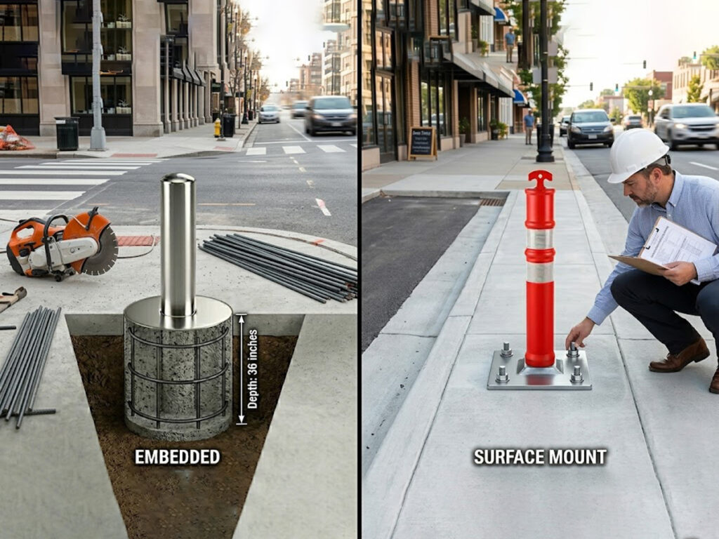
Die folgende Tabelle bietet Facility Managern eine strukturierte Entscheidungsmatrix zum Vergleich eingebetteter und oberflächenmontierter Systeme Fundament für Verkehrspoller Systeme in den Dimensionen, die für die Projektplanung und das langfristige Asset-Management am relevantesten sind.
| Vergleichsmetrik | Eingebettete Stiftung | Grundplatte zur Oberflächenmontage |
| Schlagfestigkeit | Höchste erreichbare Crash-Bewertung von K4 bis K12 | Mäßig bis gering – begrenzt durch die Scherkraft des Ankers |
| Ausgrabung erforderlich | Ja – tiefe Kernbohrung, 18″–36″+ Tiefe | Nein – nur Oberflächenbohren (Ankerlöcher) |
| Substratanforderung | Jeder stabile Boden oder neue Betonfüllung | 4″–6″ verstärkte Platte min. (durch Kernprobe verifiziert) |
| Betonspez | 2,500–4.000 PSI; ASTM C260 in Gefrier-Tau-Zonen | Vorhandene Platte muss übereinstimmen 2,500 PSI min. |
| Stückkosten & Arbeit | Höher – Ausgrabung, Betonvolumen, Heilungszeit | Unten – nur Ankerbeschläge, Fertigstellung am selben Tag |
| Zeitleiste der Installation | 2–5 Tage + 28-Tageskur vor bestimmungsgemäßem Gebrauch | 4–8 Stunden; Verkehrswiederherstellung am selben Tag |
| Dauerhaftigkeit / Flexibilität | Dauerhaft; Zum Entfernen ist ein Presslufthammer erforderlich & Plattenreparatur | Abnehmbar oder austauschbar; rekonfigurierbares Layout |
| Wartung / Ersatz | Niedrig – unter dem Gefälle versiegelt; Kein erneutes Anziehen der Befestigungselemente | Jährliche Drehmomentkontrolle; Bei Beschädigung der Platte erneut bohren |
| Frost-Tauwetter-Resilienz | Hoch – ASTM C260-Mischung + Tiefe unterhalb der Frostgrenze | Mäßig – Dichtung erforderlich; Plattenkante gefährdet |
| Crash-Rating erreichbar | Ja – ASTM F2656 / Iwa 14-1 mit PE-Ausführung | NEIN (Standard); Nur begrenzte zertifizierte Systeme |
Quelle: ASTM F2656, ACI 318-19, Iwa 14-1, ICC-ES ESR-Daten
Schritt-für-Schritt-Arbeitsabläufe bei der Fundament- und Ankerinstallation
Das am besten spezifizierte Fundament für Verkehrspoller schlägt fehl, wenn der Installationsworkflow nicht präzise ausgeführt wird. Die folgenden Verfahren stellen branchenübliche Best Practices für jeden Installationstyp dar, zusammengefasst in umsetzbaren Checklisten für Facility Manager, die die Arbeit von Auftragnehmern überwachen.
Standardarbeitsanweisung für das direkte Erdkernbohren und Betongießen
- Markieren und überprüfen Sie die Bohrstellen anhand des genehmigten Lageplans. Bestätigen 811 unterirdische Versorgungsräumung
- bevor mit dem Bohren begonnen wird.
- Kernbohren auf angegebenen Bohrdurchmesser (mindestens 3× Poller-Außendurchmesser) und Tiefe (pro Anwendungstabelle). Dokumentieren Sie die gemessene Tiefe, bevor Sie den Bohrer entfernen.
- Bohrung reinigen: Entfernen Sie alles lose Material, Trümmer, und stehendes Wasser. Überprüfen Sie die Bohrwände – alle Bereiche mit weichem Boden oder organischem Material müssen dem zuständigen Ingenieur gemeldet werden, bevor Sie fortfahren.
- Pollerschaft senkrecht stellen (Lottoleranz: 1/8 Zoll pro Fuß Schafthöhe). Befestigen Sie die Welle mit einer Querstrebe oder einer speziell angefertigten Ausrichtungsvorrichtung in ihrer Position – verlassen Sie sich nicht darauf, dass der Guss die Lotlinie hält.
- Beton kontinuierlich vom Bohrlochboden nach oben einbringen, Verwenden Sie ein Bohrrohr für Bohrungen, die tiefer sind als 24 Zoll. Mechanische Vibration (Konsolidierung) ist obligatorisch – 15 Zu 20 Sekunden pro Einfügepunkt.
- Fertigen Sie die Oberfläche so an, dass sie mindestens 0,3 mm vom Pollersockel abfällt 1/8 Zoll pro Fuß, um Wasser von der Schnittstelle zwischen Schaft und Fundament abzuleiten.
- Melden Sie sich für das Datum an, konkrete Chargenticketnummer, und angegebenem PSI. Beschilderung nach der Aushärtungszeit: “Nicht laden – Aushärten des Betons.” Nicht entfernen, bis die 28-tägige Aushärtung abgeschlossen ist oder der Zylindertest mit beschleunigter Aushärtung die Designfestigkeit bestätigt.
Nach Bestätigung des Fundamentlayouts und der Installationspositionen, Überprüfen Sie, ob der Pollerabstand den Zugangs- und Sicherheitsanforderungen entspricht, bevor Sie den Lageplan fertigstellen. Siehe die Abstandsleitfaden für Verkehrspoller für verschiedene Anwendungsszenarien.
Best Practices für die Verankerung von Bodenpollern auf vorhandenen Bodenplatten
- Führen Sie eine Plattenüberprüfung durch: Kernbohrer eine Probe pro 500 Quadratfuß der Installationszone, um die Dicke und das Vorhandensein von Bewehrungsstäben zu bestätigen. Testen Sie die Druckfestigkeit des Kerns mithilfe des ASTM C39-Zylinderbruchtests, wenn keine Plattenalter- oder Betonieraufzeichnungen verfügbar sind.
- Markieren Sie die Positionen der Ankerlöcher Verwenden Sie die Grundplatte als Vorlage. Randabstände überprüfen: Jedes Loch muss mindestens das 6-fache des Ankerdurchmessers von jeder Plattenkante entfernt sein, Riss, oder Baufuge.
- Ankerlöcher bohren mit einem Bohrhammer (Keilanker) oder Diamantkernbohrer (Epoxidanker mit einem Durchmesser von ≥5/8 Zoll). Bohren Sie bis zur angegebenen Einbettungstiefe + 1/2 Zoll für Spanfreigabe.
- Löcher reinigen (Epoxidanker): Druckluft in das Loch blasen, Mit einer Drahtbürste mit dem richtigen Durchmesser schrubben, noch einmal blasen. Wiederholen Sie den Zyklus dreimal. Verunreinigte Löcher verringern die Festigkeit der Epoxidharzbindung 30 Zu 60 Prozent.
- Installieren Sie die Anker gemäß den ESR des Herstellers: Bei Klebesystemen Epoxidharz vom Lochboden nach oben einspritzen; Ziehen Sie mechanische Anker mit dem angegebenen Wert an (Z.B., 3/4„Keilanker: 110–130 ft-lb).
- Grundplatte über Anker setzen; Unterlegscheiben und Muttern handfest anbringen, Anschließend sternförmig auf das angegebene Enddrehmoment anziehen. Installieren Sie eine Neopren- oder EPDM-Dichtung, bevor die Grundplatte angebracht wird – fügen Sie nach dem Anziehen kein Dichtungsmaterial hinzu.
- Warten Sie, bis das Epoxidharz vollständig ausgehärtet ist (24–72 Stunden bei Umgebungstemperatur, pro Hersteller ESR) vor Aufbringung der Betriebslast.
Qualitätssicherung: Prüfung der Betondruckfestigkeit und des Ankerdrehmoments
Qualitätssicherung für jeden Fundament für Verkehrspoller Die Installation erfordert eine dokumentierte Überprüfung von zwei Parametern: Betondruckfestigkeit und Ankereinbaudrehmoment.
Überprüfung der Betondruckfestigkeit: Erhalten und behalten Sie Betonchargentickets für jeden Guss. Für absturzgefährdete Anwendungen, Herstellung und Prüfung von 6 x 12 Zoll großen ASTM C39-Zylindern in Abständen von 7 und 28 Tagen. Die 28-tägige Pause muss die angegebene Auslegungsstärke erreichen oder überschreiten. Ersetzen Sie veröffentlichte Mischungsdesignstärken nicht durch tatsächliche Feldzylinderdaten – Chargenvariabilität und Feldaushärtungsbedingungen führen routinemäßig dazu 10 Zu 15 Prozentuale Abweichung von der laborzertifizierten Mischungsleistung.
Überprüfung des Ankerdrehmoments: Tragen Sie die Drehmomentwerte für jeden Ankerbolzen im Installationsprotokoll ein, Verwendung eines kalibrierten Drehmomentschlüssels mit aktuellem Kalibrierzertifikat. Für Epoxid-Ankersysteme, Führen Sie eine Pull-Test-Probenahme bei mindestens einer Probe durch 10 Prozentsatz der installierten Anker gemäß den AASHTO-Bestimmungen zur Ankerprüfung – dies ist die einzige objektive Überprüfung, dass Bohrlochreinigungs- und Injektionsverfahren korrekt durchgeführt wurden. Bewahren Sie alle Aufzeichnungen auf: Drehmomentprotokolle und Zugtestberichte sind eine wichtige Dokumentation, wenn ein Pollerausfall zu einem Haftungsanspruch führt.
Zusammenfassung der Poller-Engineering-Standards und der Projektbeschaffung
Die Auswahl des richtigen Fundamentdesigns schützt Ihre Immobilieninvestitionen und schützt Ihren Betrieb vor Fahrzeugstößen. Standort-Facility-Manager müssen die bestehenden baulichen Gegebenheiten gegen die Projektrisiken abwägen.
Die Wahl eines eingebetteten Direktvergrabungssystems bietet einen hervorragenden langfristigen Aufprallschutz für stark beanspruchte Bereiche. Umgekehrt, Ein oberflächenmontiertes System mit einer robusten Grundplatte bietet eine kostengünstige Lösung, Leicht anpassbare Lösung für Zonen mit geringer Geschwindigkeit und Innengänge in Lagerhallen.
Jede Wahl der Anlagenbereitstellung muss mit den Masterplanungszielen Ihrer Einrichtung übereinstimmen. Bevor die endgültige Beschaffung oder die Ausgrabung vor Ort beginnt, Vergleichen Sie Ihre Strukturentwürfe mit unseren umfassender Leitfaden zur Spezifikation von Verkehrspollern. Mit diesem Schritt stellen Sie sicher, dass Ihr Projekt den gesetzlichen Compliance-Rahmenbedingungen entspricht, räumliche Verteilungsregeln, und Arbeitssicherheitskennzahlen.
Häufig gestellte Fragen zu Pollertechnikstandards
Können Installateure eine oberflächenmontierte Grundplatte direkt auf einer asphaltierten Parkplatzoberfläche montieren??
NEIN. Dem Asphalt fehlt die innere Zugfestigkeit und strukturelle Steifigkeit, die zur Unterstützung mechanischer Spreizanker erforderlich sind. Bei warmen saisonalen Temperaturen, Asphalt verformt sich unter Belastung, Dies führt dazu, dass sich die Anker bei geringer Belastung lösen. Geräte mit Bodenplatte müssen auf einer Stahlbetonplatte montiert werden. Wenn es nur Asphalt gäbe, Der Installateur muss ein eingebettetes Fundamentlayout für die direkte Verlegung verwenden.
Was ist die absolute Mindestdruckfestigkeit des Betons, die für kommerzielle Verkehrsbarrieren erforderlich ist??
Die absolute Mindestdruckfestigkeit, die für Standardanwendungen zur Steuerung von Nutzfahrzeugen erforderlich ist, beträgt $2,500 Psi. Jedoch, schwere Industrieanlagen, Docks laden, und Hochsicherheitszonen, in denen schweres Gerät eingesetzt wird, erfordern eine Mindestspezifikation von 3,000 Zu 4,000 Psi-Beton, um eine Verschlechterung des Untergrunds unter Belastung zu verhindern.
Wie groß ist der erforderliche Randabstand beim Bohren von Löchern für Schwerlastgrundanker??
Zur Vermeidung von Betonkantenausbrüchen bei Stößen, Bei der Platzierung der Ankerbolzen muss ein Mindestabstand zu allen nicht unterstützten Plattenrändern eingehalten werden. Dieser Abstand muss mindestens das Fünffache des Ankernenndurchmessers betragen. Für einen 0,75'' Schwerlast-Keilanker, Die Bolzenmittellinie muss mindestens 3,75 Zoll vom Rand der Betonplatte entfernt sein.
Warum übertreffen chemische Klebeanker herkömmliche mechanische Spreizdübel in Altbeton??
Chemische Verankerungssysteme üben keinen nach außen gerichteten Expansionsdruck auf die umgebende Betonmatrix aus. Stattdessen, Das strukturelle Epoxidharz verschmilzt direkt mit den rauen Innenwänden des gebohrten Hohlraums. Dadurch werden die durch mechanische Keilhülsen verursachten lokalen Spaltspannungen eliminiert, Dadurch eignen sich chemische Anker ideal für ältere Betonplatten oder Installationen in Randnähe.
Wie führt ein Fundamentdesign mit unzureichender Frosttiefe zu langfristigen Ausrichtungsfehlern??
Wenn ein eingebettetes Fundament oberhalb der örtlichen Frostgrenze endet, Unter der Basis eingeschlossene Feuchtigkeit gefriert und dehnt sich während der Winterzyklen aus. Diese Ausdehnung erzeugt eine nach oben gerichtete Kraft, die als Frosthub bekannt ist, wodurch der Betonfundamentzylinder aus der Ausrichtung gehoben wird. Im Laufe der Zeit, Durch diese Verschiebung wird der Pfosten geneigt, ruiniert das visuelle Layout, und beeinträchtigt den umgebenden Bürgersteig.
Referenzen
- Arbeitsschutz- und Gesundheitsverwaltung. (2025). Sicherheits- und Gesundheitsvorschriften für das Bauwesen: Pflicht zur Absturzsicherung (29 CFR 1926.501).
- Berichte des ICC-ES-Evaluierungsdienstes; ACI 318-19 Kap. 17
- Bureau of Labour Statistics. (2026). Nationale Datenindizes zu Arbeitsunfällen und Bausicherheit. UNS. Arbeitsministerium.