Los responsables de los depósitos conocen bien el problema. Un lote de recortes de hombres amarillos sale del taller con un aspecto impecable. Semanas después regresa del sitio con las extremidades dobladas., bordes deshilachados, y levantar vinilo. Cada señal fallida saca a un equipo de la carretera para intercambiar acciones, y cada devolución de llamada socava la reputación del contratista. La calidad de corte inconsistente cuesta más que el material: cuesta mano de obra, retrasos en el sitio, y la confianza del cliente a medida que el escrutinio de WHS sigue aumentando.
Esta guía explica exactamente cómo hacer carteles de trabajadores de corflute amarillo que mantienen su forma y su sello bajo el viento y el clima australianos reales, para que los clientes potenciales del depósito puedan decidir, con confianza en ingeniería, Ya sea para fabricar internamente o manualmente a un especialista..
La decisión de producción: Por qué el método de fabricación determina la vida útil del letrero
Los responsables de los depósitos rara vez pierden el sueño ante el archivo de diseño. Les quita el sueño la ejecución de fabricación que falló al borde. Elección cómo hacer carteles de trabajadores de corflute amarillo es una decisión de producción, no uno creativo, y determina si un cartel sobrevive a un despliegue o a una temporada completa de rotación..
Corflute está disponible en 3 mm y 5 mm de espesor y está diseñado para uso temporal en exteriores., aunque el polipropileno puede volverse quebradizo y decolorarse después de doce a dieciocho meses en las duras condiciones de Queensland., Australia Occidental, y condiciones ultravioleta del norte de Victoria. Esa ventana de vida útil se reduce rápidamente una vez que el corte introduce puntos débiles en las extremidades, cuello, y bordes. La gestión del tráfico se combina con el tráfico en vivo, donde la falla del equipo tiene consecuencias más allá del costo.
Fabricación a nivel de depósito versus producción subcontratada: Una matriz de costo-riesgo
Construir una matriz de costo-riesgo genuina significa ir más allá del precio de etiqueta de una fresadora o una mesa de corte y tener en cuenta el costo total de propiedad.. La fabricación interna conlleva gastos de capital en maquinaria., Reemplazo continuo de cuchillas y brocas., espacio de piso, y la capacitación del operador necesaria para mantener tolerancias consistentes en toda una serie de producción.. También conlleva un coste oculto que muchos depósitos subestiman.: rehacer. Cada recorte que no pasa el control de calidad debido a un borde irregular o una extremidad desalineada ya ha consumido material., tiempo de la máquina, y mano de obra antes de que sea desguazado.
La subcontratación del troquelado supone un riesgo para un proveedor con herramientas dedicadas, pero introduce sus propias variables: cantidades mínimas de pedido, plazo de entrega, y flete desde las instalaciones del fabricante hasta el depósito. Una matriz adecuada califica ambos caminos según cuatro criterios: Costo unitario al volumen de pedido típico del depósito., tasa de retrabajo y rechazo, confiabilidad del tiempo de entrega, y las horas de mano de obra liberadas para otras tareas del patio de activos si el corte ya no se realiza en el sitio. Para la mayoría de empresas de gestión de tráfico medianas y grandes, La matriz se inclina hacia la subcontratación una vez que aumentan el volumen de pedidos y el recuento de sitios., porque el costo fijo de una matriz o prensa interna es difícil de justificar por debajo de un cierto rendimiento. Realizar esta comparación anualmente, en lugar de asumir que el status quo sigue siendo correcto, mantiene la decisión basada en el volumen actual en lugar de en el hábito histórico.
Cuando el corte interno tiene sentido (Volumen bajo, Creación rápida de prototipos)
El corte interno todavía tiene un lugar legítimo en el flujo de trabajo de un depósito, particularmente donde la velocidad importa más que la perfección absoluta de los bordes. Sustituciones puntuales y urgentes: un cartel dañado durante la noche en un lugar activo, o una solicitud de último momento de un supervisor de obra: son difíciles de justificar el envío a un fabricante externo incluso con un plazo de entrega corto. Una fresadora montada en un banco o una mesa de corte bien configurada permite que un depósito entregue una sola unidad en cuestión de horas en lugar de días..
La creación rápida de prototipos es el otro caso de uso claro. Cuando un equipo de diseño está probando una nueva proporción de silueta, un ángulo de extremidad diferente, o una ubicación de ícono revisada, Cortar un puñado de unidades de prueba internamente evita el costo y el plazo de una producción externa para algo que aún puede cambiar.. Aquí también es donde un depósito puede experimentar con la orientación de la flauta y los ajustes de corte sin comprometerse con un lote completo., refinar el archivo antes de enviarlo a una troqueladora subcontratada para la producción en volumen. La disciplina clave es saber cuándo dejar de tratar el corte interno como método de producción y comenzar a tratarlo puramente como una herramienta de prueba y contingencia: el momento en que el volumen se vuelve repetible y predecible., La economía generalmente favorece confiar el trabajo a herramientas dedicadas..
El troquelado industrial se vuelve no negociable a escala de flota
Una vez que un contratista rota el stock en múltiples sitios y múltiples equipos, el cálculo cambia por completo. A escala de flota, La calidad inconsistente de los bordes debido al corte manual o con fresadora ya no es un problema de calidad menor: es una responsabilidad agravante que se manifiesta en un aumento de las devoluciones de llamadas., vida útil más corta de la señal, y presentación inconsistente en toda la flota de sitios de una empresa. Un contratista principal que audite los activos de señalización de una empresa de gestión del tráfico notará si algunos recortes son nítidos., Bordes sellados mientras que otros muestran deshilachados o delaminación visibles., y esa inconsistencia se refleja directamente en el profesionalismo percibido..
El troquelado industrial elimina esta variabilidad al producir un resultado idéntico en cada unidad., independientemente de qué operador dirigió la prensa o qué turno produjo el lote. También desbloquea verdaderas economías de escala.: una vez construido y amortizado el troquel con regla de acero, El costo marginal de cada señal adicional cae drásticamente., y el tiempo de entrega para pedidos repetidos se acorta porque las herramientas y la lima ya están probadas. Para administradores de depósitos que supervisan docenas o cientos de sitios activos, El argumento a favor del troquelado deja de ser la estética de los bordes y se convierte en un cálculo sencillo del coste total de la flota., frecuencia de reemplazo, y coherencia de la marca en todas las zonas de trabajo en las que opera la empresa.
Comportamiento material: Cómo reacciona el plástico estriado a formas recortadas complejas
Corflute no es un sólido uniforme, es una estructura de paredes gemelas, y entenderlo es el punto de partida para cómo hacer carteles de trabajadores de corflute amarillo que se mantienen unidos en una silueta en lugar de un rectángulo. El corflute estándar de 3 mm pesa aproximadamente 800 gramos por metro cuadrado, por eso se maneja fácilmente con fijaciones básicas, mientras que los calibres más pesados intercambian peso extra por rigidez. El canal de la flauta corre en una sola dirección., Y cada curva en un recorte cruza esa veta..
Los fabricantes a menudo utilizan por defecto un stock de 5 mm para cualquier cosa más grande que un panel de marco en A estándar.. El espesor añadido de la pared resiste la flexión que causa grietas finas en puntos de silueta estrechos.. La flauta corrugada de 3 mm y 5 mm de espesor se puede cortar en cualquier tamaño o forma compleja., incluyendo círculos, hexágonos, y contornos irregulares, aunque el tamaño de hoja estándar es de 2400 mm por 1200 mm antes de que sea necesario unir. Conseguir que este comportamiento material sea correcto es importante para cómo hacer carteles de trabajadores de corflute amarillo que sobreviven a más de un despliegue.
Densidad de Corflute y selección GSM para mayor durabilidad de la silueta
Seleccionar el calibre y GSM correctos es una cuestión de hacer coincidir el material con el ciclo de trabajo en lugar de optar por lo que ya está en el estante.. Una hoja de 3 mm de aproximadamente 800 gramos por metro cuadrado es la opción práctica para implementaciones de rotación corta: señales que se utilizarán para un solo trabajo, un cierre de fin de semana, o una campaña que dura algunas semanas antes de ser retirada o recortada. Su peso más ligero también reduce la fatiga de manipulación de los equipos que cargan y descargan carteles varias veces al día., y mantiene bajos los costos de flete cuando un depósito envía lotes grandes a sitios remotos.
Cuando se espera que un recorte rote en varios sitios durante un período de meses, o donde se montará en altura o en una posición expuesta, la densidad adicional del material de 5 mm vale el peso y el costo adicionales. La pared más gruesa resiste la microflexión acumulativa que experimenta una hoja más liviana cada vez que se carga., transportado, y vuelto a montar, que es exactamente el tipo de tensión repetida que eventualmente causa grietas por fatiga en los puntos estrechos de una silueta.. Una regla útil para los compradores de depósitos es tratar el GSM y el grosor como un presupuesto de durabilidad.: Gaste más material donde el letrero verá más ciclos de manipulación y más exposición al viento., y reserve el ancho de vía más ligero para períodos realmente cortos., aplicaciones de bajo manejo donde la rentabilidad importa más que la resiliencia a largo plazo.
Por qué la anatomía humana curva enfatiza las paredes de la flauta de manera diferente que los letreros de bordes rectos
Un letrero rectangular estándar solo le pide a la estructura de la flauta que haga un trabajo: resistir la flexión a lo largo de dos bordes rectos, normalmente donde se encuentra con una estaca o un marco. Una silueta humana pide al mismo material un trabajo mucho más exigente, porque el contorno cambia de dirección continuamente: alrededor de la cabeza, a través de los hombros, por cada brazo, en la cintura, y retroceder a lo largo de las piernas. Cada uno de estos cambios de dirección representa un punto donde la pared de la flauta se corta en ángulo con respecto a su propia fibra en lugar de a lo largo de ella., y un corte en ángulo es inherentemente más débil que uno que corre paralelo a las costillas internas.
El problema se agrava en los puntos más estrechos de la silueta: las muñecas., tobillos, y el cuello, porque estas áreas tienen el menor ancho de material para distribuir la carga. Una ráfaga de viento o un golpe durante el transporte que un letrero rectangular absorbería sin problemas puede concentrar suficiente tensión en un cuello o muñeca estrechos para iniciar una grieta que se propaga a lo largo del canal de la flauta tras exposición repetida.. Esta es precisamente la razón por la que los fabricantes tratan un recorte humano como un desafío estructuralmente distinto de un letrero de panel estándar., y por qué las decisiones sobre la orientación de la flauta, calibre de hoja, y el método de corte deben reconsiderarse específicamente para la geometría de la silueta en lugar de tomarlos prestados al por mayor de la producción de letreros rectangulares planos.
Alternativas de sustrato para regiones con fuertes vientos
Para depósitos que operan en ambientes con vientos realmente extremos: corredores costeros expuestos, pasos elevados de autopistas, o regiones interiores abiertas propensas a fuertes ráfagas: la corfluta puede no siempre ser la opción de sustrato más duradera, incluso con un calibre de 5 mm y con la orientación correcta de la flauta. Los sustratos más pesados, como tableros de espuma de PVC o paneles compuestos de aluminio, ofrecen mayor rigidez y resistencia a la flexión., a costa de peso adicional, mayor costo de material, y menor facilidad de manipulación y transporte in situ.
La elección correcta depende de equilibrar la frecuencia de implementación con la gravedad de la exposición.. Un recorte que se montará de forma semipermanente en una ubicación conocida con fuertes vientos puede justificar la inversión en un sustrato más rígido., mientras que un letrero que gira con frecuencia entre sitios de exposición variable suele funcionar mejor con una corflauta con el calibre y la orientación de la flauta correctos., combinado con una técnica adecuada de montaje y sellado de bordes. Cuando los gerentes de los depósitos pesan corflute frente a sustratos de mayor calibre para condiciones extremas de viento costero o interior, Vale la pena comparar los datos de rendimiento en nuestro desglose detallado que compara corflute., aluminio, y PVC en todo el peso, rigidez, y costo, Dado que la decisión correcta sobre el sustrato depende en última instancia del patrón de implementación específico y el perfil de exposición de cada sitio de la flota..
La dirección de la flauta & Desafío de integridad estructural
La dirección de la flauta es la variable que más se pasa por alto en la fabricación de siluetas. Equivocarse es la forma más rápida de producir señales que se pliegan en la primera ráfaga fuerte.. Depot lidera la investigación cómo hacer carteles de trabajadores de corflute amarillo casi siempre encontramos que este es el paso que la producción manual omite primero. La orientación de la flauta es importante para la instalación de estacas: las flautas deben correr verticalmente para letreros montados en estacas, ya que esto alinea las nervaduras internas con la estaca de montaje y resiste la flexión. En una silueta humana, esa misma alineación vertical a través del torso evita que los brazos se caigan.
Los proveedores advierten habitualmente a los compradores de depósito que especifiquen la orientación de la flauta desde el principio.. Si no se especifica la dirección de la flauta, Los letreros se producen en cualquier orientación que proporcione el mejor rendimiento del material., y solicitar una dirección específica generalmente aumenta el costo debido al desperdicio. Para un recorte de hombre amarillo., ese valor predeterminado puede colocar flautas horizontalmente a lo largo de los hombros, precisamente la orientación que causa la caída de las extremidades y el pliegue de las orejas..
Leer la dirección de la fibra antes de cortar: Una lista de verificación del piso del depósito
Confirmar la dirección de la ranura antes de realizar un solo corte debe ser un procedimiento permanente en cualquier piso de depósito., porque los canales no siempre son obvios a simple vista, especialmente en hojas más oscuras o muy impresas. El método más confiable es sostener la hoja frente a una fuente de luz; las nervaduras internas se mostrarán como líneas paralelas tenues que recorren la dirección del canal.. Donde las condiciones de iluminación lo hacen difícil, Pasar una uña o el borde plano de una herramienta sin filo por la superficie revelará un patrón de cresta sutil que confirma la orientación mediante el tacto en lugar de la vista..
Una lista de verificación simple del piso del depósito debe incluir: verificar la dirección de la flauta con el albarán de entrega del proveedor antes de que la hoja salga del palé, marcar la dirección confirmada directamente en la película protectora de la hoja con un marcador permanente antes de comenzar el corte, y comparar esa dirección con la orientación prevista del archivo vectorial antes de realizar el primer corte. Este último paso es importante porque una lima preparada para una orientación de flauta producirá un letrero estructuralmente comprometido si se anida en una hoja que corre en sentido opuesto.. Incorporar esta lista de verificación a un procedimiento operativo estándar, en lugar de confiar en la memoria de un operador experimentado, protege contra la inconsistencia que ocurre cuando diferentes turnos o personal nuevo maneja la tarea de corte.
Por qué las extremidades alineadas horizontalmente se pliegan bajo las ráfagas de viento en la carretera
Cuando el brazo de una silueta o la herramienta levantada se corta con la flauta a lo ancho en lugar de a lo largo, esa extremidad efectivamente no tiene soporte estructural interno que se extienda en la dirección que necesita para resistir la flexión. Las pieles exteriores planas de polipropileno proporcionan cierta rigidez por sí solas., pero sin las nervaduras internas que refuerzan el vano longitudinalmente, la extremidad se comporta más como un colgajo que como una extensión rígida del signo.
En la práctica, Esto significa que una ráfaga en la carretera, que normalmente excede las cargas que experimenta un letrero en un patio de depósito protegido, flexionará la extremidad repetidamente en su sección transversal más débil., generalmente donde se une al torso o al hombro. La flexión repetida bajo cargas de viento cíclicas es un mecanismo de fatiga clásico.: No es necesario que el material falle con la primera ráfaga., pero cada evento de flexión debilita ligeramente la piel de polipropileno hasta que se forma un pliegue visible., seguido de un pliegue o desgarro completo. Por eso los depósitos que informan “brazos cayendo” o “las orejas dobladas” En los recortes del hombre amarillo casi siempre se trata de un problema de dirección de la flauta en lugar de un problema de calidad del material., y por qué corregir la orientación en la siguiente tirada de producción normalmente resuelve el problema por completo sin necesidad de cambiar el calibre de la hoja o el proveedor..
Técnicas de refuerzo cruzado para siluetas con brazos anchos
No todos los resúmenes de diseño permiten una simple, silueta de brazos a los costados. Algunos íconos de seguridad indican un brazo extendido sosteniendo un bate para detener la velocidad, una mano levantada, o una postura amplia que extiende el diseño mucho más allá de una sola columna alineada con estrías. En estos casos, Los fabricantes necesitan una técnica que preserve la integridad estructural sin forzar un rediseño del ícono en sí..
El enfoque más confiable es anidar el elemento estructural más ancho del diseño (generalmente el brazo o la pierna extendidos) paralelo a la dirección del canal de la hoja., incluso si esto significa aceptar un margen de recorte más grande alrededor del resto de la silueta. Esto trata efectivamente al brazo como su propio minipanel con soporte de flauta completo a lo largo de toda su longitud., en lugar de intentar alinear todo el cuerpo con una única orientación que inevitablemente comprometa alguna otra extremidad.
Cuando un diseño realmente no se puede anidar de esta manera sin un desperdicio excesivo, Algunos fabricantes utilizan una tira de refuerzo secundaria (una tira delgada de corflute a juego o un listón rígido) adherida a lo largo de la parte inferior de la extremidad vulnerable durante el ensamblaje., agregando efectivamente un miembro de refuerzo que la dirección de la flauta por sí sola no puede proporcionar. esto es mas lento, Solución que requiere más mano de obra y generalmente está reservada para señales de alto valor o de larga duración en lugar de existencias de rotación corta., donde aceptar el material sobrante del anidamiento inteligente es la solución más rentable.
Preparación del archivo de diseño antes de comenzar el corte
Sin método de corte, por muy preciso que sea, puede corregir un archivo vectorial mal preparado, Y aquí es donde la mayoría de las operaciones internas tienen problemas antes de que la hoja toque la hoja.. cualquier proceso para cómo hacer carteles de trabajadores de corflute amarillo tiene que comenzar en la pantalla, no la mesa de corte. Compensación de corte, caminos cerrados, y el radio mínimo del nodo deben configurarse correctamente para el método de corte previsto..
Las brocas de enrutador exigen un radio mínimo más amplio en las esquinas interiores que un troquel con regla de acero., por lo que un archivo elaborado con un método rara vez se transfiere limpiamente al otro. Antes de calibrar su maquinaria de corte, debe comenzar con un modelo vectorial estructuralmente sólido. Para ahorrar tiempo a tu equipo, puedes descargar nuestro pre-escalado, plantilla vectorial lista para producción y conjunto de bloques CAD.
Limpieza de rutas vectoriales para rutas de herramientas compatibles con enrutadores
Un archivo vectorial limpio es el mayor predictor de una ejecución de producción fluida, y la limpieza debe realizarse mucho antes de que el archivo llegue al software CNC. Cada punto de anclaje a lo largo del contorno de la silueta debe asentarse con precisión en un único punto continuo., camino cerrado, sin nodos perdidos, duplicar líneas superpuestas, o espacios involuntarios que quedaron de revisiones de diseño anteriores. Un camino abierto, incluso un espacio invisible en niveles de zoom normales, hará que un enrutador se salte esa sección por completo o retroceda y la vuelva a cortar., Ambos producen un borde visiblemente defectuoso y una pérdida de tiempo de la máquina..
Los líderes de producción en depósito deben incorporar una verificación previa al vuelo estándar en su flujo de trabajo.: acercar al menos 400 por ciento en cada cambio de dirección en el contorno para confirmar que el camino está realmente cerrado, elimine cualquier ruta duplicada u oculta que haya quedado de iteraciones anteriores del diseño, y confirme que las secciones curvas utilicen una cantidad razonable de puntos de anclaje en lugar de una densidad excesiva que puede hacer que el enrutador tartamudee en radios estrechos.. Los archivos exportados desde software de ilustración a veces introducen una complejidad innecesaria en áreas curvas, y simplificar estos trazados, al tiempo que se preserva la forma de silueta deseada, produce recorridos de herramienta más suaves y un borde acabado más limpio en los brazos., cuello, y otras secciones muy curvadas del diseño..
Cálculos de compensación de corte para el ancho de la hoja y el espesor de la matriz
Kerf es el material eliminado por la propia herramienta de corte., y no compensarlo es una de las razones más comunes por las que un recorte terminado resulta más pequeño que el archivo de diseño previsto.. Para corte de enrutador, el desplazamiento del corte debe tener en cuenta el diámetro de la broca en uso, dado que la ruta del enrutador corre a lo largo del centro de la broca en lugar de a lo largo de su borde exterior, lo que significa que la lima debe desplazarse hacia afuera aproximadamente la mitad del diámetro de la broca para producir una pieza que coincida con las dimensiones previstas.. Para troquelado con regla de acero, el ajuste equivalente se refiere al grosor y bisel de la propia regla, que se comporta de manera diferente a una broca giratoria y requiere su propio cálculo de compensación específico de las especificaciones del fabricante del troquel.
La práctica más confiable es incorporar este desplazamiento en el archivo vectorial como una capa de corte dedicada., en lugar de depender del operador de la máquina para compensar manualmente en el punto de producción. La compensación manual introduce variabilidad entre operadores y turnos, e incluso las pequeñas inconsistencias se acumulan a lo largo de una producción completa., lo que lleva a un lote de recortes con dimensiones visiblemente inconsistentes. Cuando un depósito trabaja con más de un método de corte, por ejemplo, un enrutador interno para prototipos y un troquel subcontratado para producción en volumen, manteniendo dos versiones de archivos separadas, cada uno con el desplazamiento de corte correcto incorporado para su método respectivo, evita la confusión y la desviación dimensional que se produce cuando una sola lima se ajusta manualmente de forma diferente cada vez que se utiliza.
Alinear la ubicación del texto y los iconos antes de la fabricación
Antes de que una lima se acerque a una máquina cortadora, cada pedazo de texto, icono grafico, y el símbolo de seguridad en el diseño debe estar colocado y dimensionado correctamente en relación con las dimensiones físicas de la silueta terminada., no sólo sus proporciones en pantalla. Esto es importante porque los estándares de legibilidad en carretera especifican alturas mínimas de letras y proporciones de símbolos basadas en la distancia de visualización esperada y la velocidad del vehículo., y estos estándares no se escalan automáticamente si se cambia el tamaño de un diseño sin ajustar las dimensiones del texto y los iconos para que coincidan.. Una silueta que se ve correctamente proporcionada en un monitor puede terminar con letras de tamaño insuficiente una vez impresas a escala física completa si se omite este paso..
Asegúrese de que las alturas de sus letras físicas y sus íconos gráficos se alineen con las normas de seguridad en la carretera revisando nuestra evaluación de los estándares de legibilidad y los símbolos de seguridad de la UA.. Más allá del cumplimiento, La colocación correcta también protege el diseño de errores en la etapa de fabricación.: El texto o los iconos colocados demasiado cerca de un borde cortado o de un punto de silueta estrecho corren el riesgo de recortarse parcialmente durante el corte., o sentarse en una sección del letrero propensa a flexionarse y agrietarse bajo la carga del viento. Crear un pequeño margen de amortiguación entre cualquier elemento gráfico crítico y el borde estructural más cercano, particularmente en el cuello., muñecas, y tobillos: mantiene intactos el cumplimiento y la durabilidad una vez que la lima pasa de la pantalla a la hoja.
Corte Manual & Enrutamiento CNC versus troquelado industrial con regla de acero
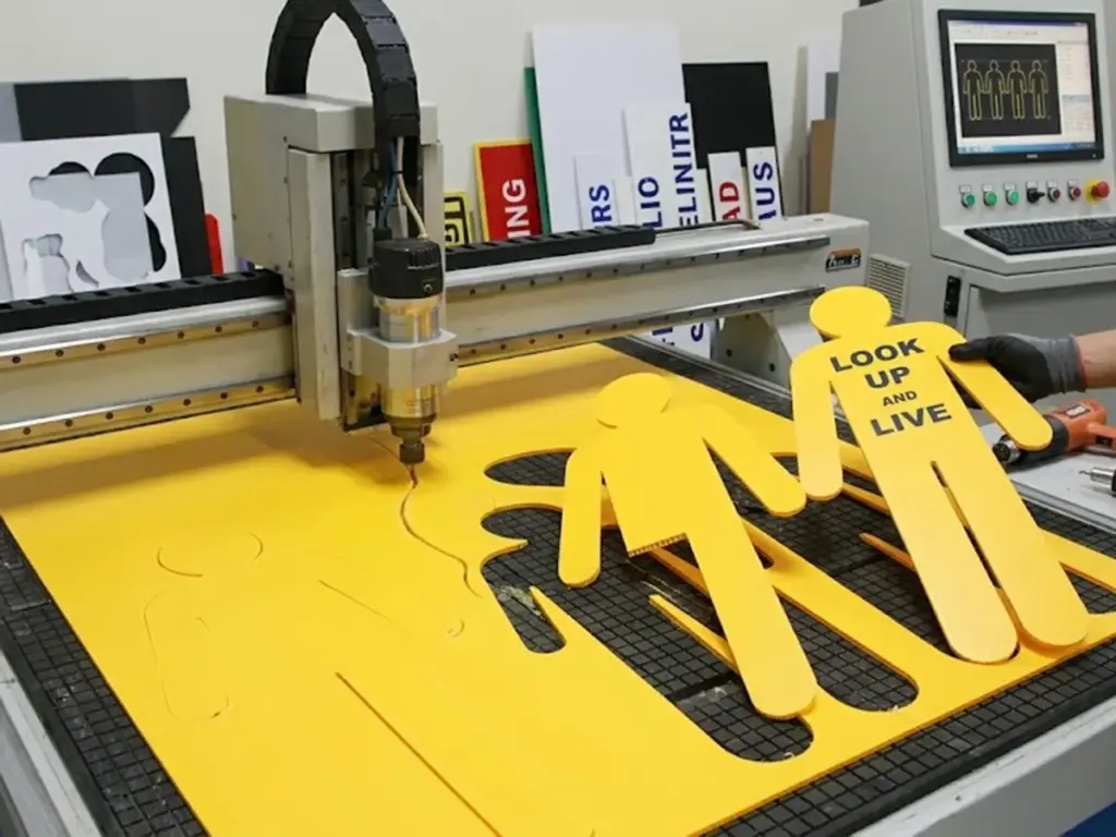
Esta es la sección que todo responsable de depósito pregunta cómo hacer carteles de trabajadores de corflute amarillo finalmente llega, porque en el método de corte es donde se gana o se pierde la calidad. Una navaja y una regla pueden producir un prototipo aceptable, pero una vez que un cortador sigue una muñeca curva o un tobillo estrecho, el arrastre de la hoja se convierte en enemigo de un filo limpio.
Los enrutadores CNC resuelven el problema de la velocidad pero introducen otro: una broca giratoria tritura en lugar de cortar la pared de la flauta en radios estrechos, dejando un fibroso, Borde abierto que se comporta como una mecha para la humedad.. Las prensas industriales troqueladoras con reglas de acero resuelven ambos problemas de una sola vez, comprimir y sellar la pared de la flauta a medida que la hoja la atraviesa en lugar de arrastrarla a través de ella..
| Método de corte | Calidad de borde | Más adecuado para | Costo unitario relativo en volumen |
| cuchillo utilitario manual | Bruto, dependiente del operador | Prototipos, reemplazos individuales | Alto costo laboral por unidad |
| enrutador cnc | Limpio en tramos rectos, irregular en curvas cerradas | Tiradas pequeñas y medianas, piezas únicas personalizadas | Moderado, escala mal después de la configuración |
| Prensa troqueladora con regla de acero | Comprimido, borde consistentemente sellado | Ejecuciones de producción a escala de flota | Bajo costo por unidad una vez que se amortizan las herramientas |
Evaluación comparativa basada en la práctica de fabricación de la industria.; Consulte las referencias a continuación para obtener materiales de respaldo y fuentes de estándares..
Corte manual con cuchilla multiusos: tolerancias, Limitaciones, y costo laboral
El corte manual sigue siendo el punto de entrada más accesible para cualquier almacén, requiriendo nada más que una cuchilla afilada, una regla estable, y una mano firme, pero sus limitaciones se hacen evidentes rápidamente una vez que la precisión y la repetibilidad importan.. Un operador experto que utilice una hoja nueva a una velocidad constante 30 a 45 El ángulo de grados puede producir cortes rectos razonablemente limpios., pero las tolerancias tienden a variar a lo largo de un cambio a medida que el filo de la hoja se degrada y la fatiga del operador aparece., particularmente en secciones curvas donde la presión y el ángulo constantes son más difíciles de mantener con la mano.
Cada corte curvo de una silueta: la parte inferior de un brazo., el interior de un codo doblado, la estrecha forma cónica de un tobillo añade un tiempo significativo al operador en comparación con una regla, y cada una de estas curvas también conlleva un mayor riesgo de rechazo si la hoja se engancha o se arrastra de manera desigual. Esta combinación de tiempo de corte prolongado y tasa de rechazo elevada es la razón por la cual el corte manual rara vez supera un pequeño puñado de unidades terminadas por turno una vez que los estándares de calidad se aplican de manera constante.. Para un depósito que evalúa el costo real de producción, Las horas de mano de obra consumidas por el corte manual, incluido el tiempo dedicado a volver a cortar las unidades rechazadas, a menudo superan los ahorros aparentes que se obtienen al evitar la inversión en máquinas., particularmente una vez que el volumen va más allá de los reemplazos ocasionales de una sola unidad.
Corte con enrutador CNC: por qué el corte por arrastre destruye las paredes de las ranuras en radios estrechos
El enrutamiento CNC resuelve los problemas de consistencia y velocidad inherentes al corte manual, Permitir que un depósito programe un contorno de silueta una vez y lo reproduzca con precisión en muchas hojas.. Sin embargo, El mecanismo físico de enrutamiento (una broca giratoria que elimina el material mediante contacto abrasivo en lugar de una sola acción de corte) crea una debilidad específica cuando la trayectoria de la herramienta sigue un radio interior estrecho., como la curva en la muñeca, tobillo, o la parte inferior de un brazo levantado.
En estas curvas cerradas, la broca giratoria se arrastra a través de la pared de la flauta en lugar de cortarla limpiamente en un solo movimiento, y esta acción de arrastre tiende a desgarrar la estructura interna de la nervadura en lugar de cortarla limpiamente.. El resultado es una fibra, Borde ligeramente deshilachado donde se tiran los hilos individuales de polipropileno en lugar de cortarlos., y esta textura fibrosa es exactamente lo que permite que la humedad penetre en el canal abierto de la flauta con el tiempo.. Tanto la velocidad de avance como las RPM del husillo influyen en la gravedad de este efecto: una velocidad de avance demasiado rápida en relación con la velocidad del husillo aumenta el arrastre y el desgarro., mientras que una combinación adecuadamente ajustada puede minimizar, pero rara vez eliminar, el problema por completo en radios realmente estrechos.. Esta es la razón principal por la que el enrutamiento CNC, aunque más rápido y consistente que el corte manual, todavía no llega al troquelado cuando la prioridad es el sellado de bordes y la resistencia al agua a largo plazo.
Troquelado con prensa industrial con regla de acero: compresión, Velocidad, y beneficios del sellado de bordes
El troquelado industrial funciona según un principio físico completamente diferente del corte manual y con fresadora.. En lugar de eliminar el material mediante una acción de arrastre o abrasiva, una matriz con regla de acero montada en una prensa hidráulica o mecánica impulsa una hoja afilada hacia abajo a través de la hoja en un solo golpe, Cortar la pared de la flauta limpiamente y al mismo tiempo comprimir el borde cortado bajo el tonelaje de la prensa.. Esta compresión es la diferencia mecánica clave que produce un sellado en lugar de un abierto., borde fibroso.
Porque todo el contorno de la silueta se corta con un trazo sincronizado en lugar de trazarse punto por punto., El troquelado también es dramáticamente más rápido por unidad una vez que se ha construido el troquel., lo que lo convierte en la opción clara para cualquier depósito que vaya más allá de pequeños lotes de prototipos. El costo inicial de mecanizar un troquel con regla de acero es la principal barrera de entrada., pero ese costo es fijo y se amortiza rápidamente a lo largo de una serie de producción., lo que significa que el costo unitario cae drásticamente a medida que aumenta el volumen: la curva de costos opuesta al corte manual, donde el costo laboral por unidad se mantiene aproximadamente constante independientemente del volumen. Para gerentes de depósitos que sopesan la calidad de vanguardia, velocidad de producción, y el coste total de la flota juntos, El troquelado es generalmente el único método que satisface los tres simultáneamente a escala real..
Sellado de bordes & Impermeabilización para las condiciones del campo australiano
Un borde no sellado es la principal causa de fallo prematuro de la señal. El canal de flauta abierto actúa como una pajita., aspirando la humedad directamente debajo de la cara del vinilo impreso. Saltarse este paso es el error más común que cometen los deportistas al hacer ejercicio. cómo hacer carteles de trabajadores de corflute amarillo que duran más allá de una sola temporada de lluvias. Una vez que el agua se asienta dentro del canal, Sigue el despegue del adhesivo., y el letrero se despega de adentro hacia afuera antes de que la impresión de la superficie muestre algún desvanecimiento..
En las duras condiciones ultravioleta australianas, la superficie de polipropileno puede comenzar a decolorarse y volverse quebradiza dentro de doce a dieciocho meses. Ese cronograma se acorta considerablemente cuando los bordes quedan sin sellar.. Sellado térmico del borde cortado., grabándolo, o confiar en la compresión de un troquel con regla de acero son las tres opciones prácticas disponibles. No son igualmente efectivos.
Cómo las flautas sin sellar permiten la entrada de agua debajo de las capas de vinilo impreso
El mecanismo detrás de la falla impulsada por los bordes es sencillo una vez que se comprende la estructura interna de la corfluta.. Cada canal de flauta corre a lo largo de la hoja como un canal abierto., tubo hueco, Sellado solo donde las dos pieles exteriores de polipropileno se unen con las nervaduras internas.. Cuando un borde cortado se deja abierto, como sucede con el corte manual áspero o los bordes de fresado triturados, ese tubo hueco se convierte en un punto de entrada directo para la lluvia., condensación, e incluso agua de lavado procedente de la limpieza., todo lo cual puede viajar distancias considerables a lo largo del canal una vez dentro.
Una vez que entra la humedad, no se queda simplemente sentado pasivamente en el borde; Se absorbe a lo largo de la estructura interna de las costillas mediante acción capilar., extendiéndose mucho más allá de la línea de corte inmediata y alcanzando áreas del letrero donde el vinilo impreso o la capa de tinta de impresión directa está adherida a la cara frontal. Uniones adhesivas, ya sea a partir de una superposición de vinilo impreso o de un soporte de montaje, son particularmente vulnerables a la exposición sostenida a la humedad desde debajo, Dado que la mayoría de los adhesivos están diseñados para resistir la intemperie de la superficie en lugar de la saturación interna.. Esta es la razón por la que un letrero no puede mostrar daños superficiales visibles ni decoloración alguna, aunque ya esté fallando estructuralmente desde el interior., y por qué confiar únicamente en la inspección visual de la cara impresa es una forma poco confiable de juzgar la vida útil restante de un recorte.
Comparación del termosellado, Grabación de bordes, y métodos de sellado por compresión
Los depósitos generalmente tienen tres opciones prácticas para cerrar un borde de flauta abierto., y cada uno viene con una compensación distinta entre efectividad, mano de obra agregada, y costo. El termosellado utiliza una cuchilla o herramienta calentada para derretir el borde cortado del polipropileno cerrado., fusionar las dos pieles exteriores a lo largo de la línea de corte. Es efectivo cuando se hace de manera correcta y consistente., pero requiere una herramienta de termosellado dedicada, un operador capacitado, y un paso de producción adicional realizado después de cada corte, lo que significa que agrega tiempo y costo de mano de obra a cada unidad producida..
El encintado de bordes implica la aplicación de una cinta adhesiva resistente a la intemperie a lo largo del borde cortado para bloquear físicamente la entrada de humedad.. Es más rápido de aplicar que el termosellado y requiere menos equipo especializado., pero la adhesión de la cinta en sí misma puede degradarse bajo la exposición a los rayos UV durante el mismo período de doce a dieciocho meses que se espera que corflute sirva en exteriores., lo que significa que el sello es tan duradero como la propia resistencia a la intemperie de la cinta.. Sellado por compresión, en contraste, logra el cierre del borde como un subproducto inherente de la carrera de corte en sí: el tonelaje de la prensa comprime la pared de la ranura en el momento del corte, sin paso de sellado separado, sin consumibles adicionales, y sin tiempo de mano de obra adicional por unidad. Para depósitos que producen en cualquier volumen significativo, Esta ventaja de sellado incorporada es uno de los argumentos más sólidos a favor del troquelado, frente a los métodos de producción manuales o basados en fresadoras..
Requisitos de sellado específicos del clima en todas las regiones de Australia
La variación climática de Australia significa que el sellado de bordes no puede tratarse como un sistema uniforme., Especificaciones únicas para todos los depósitos y regiones.. Los depósitos costeros enfrentan una combinación de mayor humedad ambiental y exposición a la sal en el aire, Ambos aceleran la entrada de humedad y también pueden contribuir a la degradación del adhesivo a un ritmo más rápido que en las condiciones del interior.. Las regiones tropicales y del norte añaden una intensa exposición a los rayos UV y períodos estacionales de alta humedad, lo que agrava el riesgo de que se desarrolle simultáneamente tanto la entrada de agua por los bordes como la fragilidad del polipropileno a nivel de la superficie..
Las regiones áridas del interior presentan un desafío diferente pero igualmente importante: mientras que la humedad y las precipitaciones son menores, El intenso calor diurno seguido del enfriamiento nocturno hace que el polipropileno se expanda y contraiga repetidamente, que puede abrir gradualmente un borde mal sellado incluso sin exposición directa al agua, preparándolo para que falle rápidamente una vez que llueve. Los administradores de depósitos que operan en múltiples zonas climáticas deberían considerar el sellado de bordes como una especificación obligatoria independientemente de la región., pero también debería considerar la posibilidad de actualizar a poblaciones de calibre más pesado o métodos de sellado más rigurosos específicamente para sitios costeros y tropicales., donde la combinación de humedad, sal, y la exposición a los rayos UV crea las condiciones más exigentes que probablemente enfrentará un letrero recortado en cualquier parte del país..
Flujo de trabajo de creación de prototipos: Desde el primer corte hasta la plantilla lista para producción
Saltar directamente de un archivo de diseño a una producción completa es la forma en que los depósitos descubren un error en la dirección de la flauta o en el corte después de que ya se han cortado quinientas unidades.. Una etapa disciplinada de creación de prototipos es lo que separa un proceso repetible para cómo hacer carteles de trabajadores de corflute amarillo de un costoso juego de adivinanzas. Un lote corto, probado en condiciones realistas, detecta problemas mientras la solución todavía cuesta un puñado de hojas.
Los datos de campo de los equipos de control de tráfico australianos muestran por qué las pruebas en condiciones reales son más importantes que la inspección en banco por sí sola.. A lo largo de más de 1,600 controladores de tráfico encuestados en Australia y Nueva Zelanda en 2025, El cuatro por ciento informó haber sido atropellado por un vehículo en el último año., y los cuasi accidentes con conductores distraídos o que van a exceso de velocidad siguen siendo un hecho semanal para muchos. Una señal que falla estructuralmente en ese entorno agrega riesgo a una fuerza laboral ya expuesta.
Creación de un lote de prototipos físicos para pruebas estructurales
Un lote de prototipos significativo no es una única unidad perfecta cortada en condiciones ideales de banco: es una pequeña, Conjunto deliberadamente variado de tres a cinco señales que reflejan la gama real de condiciones que enfrentará el producto terminado en el campo.. Esto significa variar el método de montaje en todo el lote., probar al menos una unidad en un piquete de estrella o estaca en H, otro en una valla de barrera portátil mediante bridas, y si es relevante, uno montado en un marco en A, ya que cada método de montaje pone tensión en diferentes puntos de la silueta.
También significa incluir deliberadamente unidades cortadas en ambos extremos de cualquier tolerancia que el depósito esté probando, por ejemplo, si aún se están finalizando la dirección de la flauta o el desplazamiento de la sangría, cortar un lote con cada configuración candidata en lugar de comprometerse temprano con una única configuración. Este enfoque comparativo convierte la etapa del prototipo en una recopilación de datos genuina en lugar de una simple verificación de aprobación y falla., dando al depósito evidencia concreta de qué combinación de orientación de la flauta, calibre de hoja, y el método de montaje funciona mejor antes de que esa decisión se bloquee en una producción completa de potencialmente cientos de unidades..
Montaje de prueba in situ y registro de exposición al viento
Una vez construido el lote de prototipos físicos, el siguiente paso es implementarlo en condiciones que realmente se asemejen al uso de un sitio en vivo en lugar de un patio de depósito protegido. Esto significa montar cada unidad en un lugar de trabajo real o en una ubicación exterior representativa., usando el mismo método de fijación: piquetes de estrella, bridas para cables, o marco en A, que se utilizará en la implementación de producción, y dejarlo en su lugar durante las condiciones diarias normales en lugar de quitarlo al final de cada turno..
El registro es lo que convierte esta prueba en datos de ingeniería útiles en lugar de una observación informal.. Para cada prototipo, registrar el método de montaje, exposición aproximada al viento en el sitio (utilizando datos meteorológicos locales o una simple lectura de anemómetro en el sitio cuando esté disponible), el tiempo que el cartel permaneció montado, y un registro fotográfico fechado de su estado en cada check-in. Este registro resulta invaluable si alguna unidad muestra signos tempranos de caída de las extremidades., levantamiento de borde, o deformación de la flauta, porque permite al depósito rastrear la falla hasta una combinación específica de método de montaje, duración de la exposición, y condición del viento, en lugar de adivinar la causa después del hecho. Durante varios ciclos de prototipo, Estos datos también crean un punto de referencia interno para la vida útil esperada en las condiciones típicas del sitio del depósito..
Criterios de aprobación antes de comprometerse con una producción completa
Un prototipo sólo debe aprobarse para producción a gran escala una vez que haya superado un plazo definido., conjunto escrito de criterios de aprobación, basándose en una impresión general de que “se ve bien” Así es como los defectos evitables llegan a un pedido de quinientas unidades.. Como mínimo, Los criterios de aprobación deben exigir que el prototipo haya sobrevivido al manejo y transporte de rutina sin grietas visibles en el cuello., muñecas, o tobillos, que se ha montado en el sitio durante al menos un ciclo climático completo, incluido un período de viento sostenido y al menos un evento de lluvia, y que los bordes cortados no muestren ningún desgaste visible, delaminación, o manchas de humedad tras la inspección.
La aprobación también debe incluir una verificación dimensional con respecto al archivo vectorial original., Confirmar que la compensación de corte produjo una pieza terminada que coincide con las medidas previstas dentro de una tolerancia aceptable., y una confirmación visual de que la dirección de la ranura coincide con las especificaciones acordadas con el proveedor o el equipo de corte interno.. Solo una vez que se hayan cumplido todos los criterios de esta lista de verificación., e idealmente documentado con fotografías y medidas para referencia futura., ¿Debería un depósito comprometerse a escalar el diseño a un lote de producción completo?, ya sea que la producción se realice internamente o a través de un socio de troquelado subcontratado.
Escalando desde el prototipo hasta la implementación de flotas masivas
Una vez que un prototipo pasa la aprobación, La conversación pasa de la artesanía a la logística.. plazo de entrega, almacenamiento, y la curva de costo unitario con un volumen de flota genuino entran en juego. Escalada cómo hacer carteles de trabajadores de corflute amarillo desde un prototipo de banco hasta una implementación en toda la flota es un problema tanto de la cadena de suministro como de fabricación.. El informe más reciente de Safe Work Australia muestra que la tasa de mortalidad nacional se sitúa en 1.3 por 100,000 trabajadores, Los incidentes con vehículos siguen siendo la principal causa.. Cada activo en la carretera, incluyendo un letrero de trabajador recortado, se encuentra dentro de ese sistema de seguridad más amplio.
Cuando la producción supera la capacidad del depósito, Comprender las estructuras de precios por volumen se vuelve esencial: nuestra guía sobre abastecimiento y adquisiciones a granel desglosa los niveles de costos según los tipos de proveedores..
Umbrales de precios basados en el volumen para tiradas de producción troqueladas
Los precios del troquelado rara vez escalan linealmente;, la mayoría de los fabricantes estructuran los precios en niveles escalonados donde el costo por unidad cae significativamente una vez que un pedido cruza umbrales de volumen específicos, ya que estos umbrales generalmente se alinean con un anidamiento de láminas más eficiente, tiradas de prensa ininterrumpidas más largas, y una mejor amortización del coste de las herramientas en un lote más grande. Un depósito que ordena cincuenta unidades a la vez puede estar pagando una tarifa por unidad sustancialmente más alta que uno que hace un solo pedido de doscientas unidades., aunque el diseño subyacente y el troquel son idénticos.
Solicitar un programa formal de precios escalonados a un socio de fabricación, en lugar de depender de una cotización única para un solo tamaño de pedido, brinda a los equipos de finanzas y adquisiciones de un depósito la información necesaria para modelar adecuadamente el costo total de la flota.. Esto es particularmente valioso al planificar un presupuesto anual para el reemplazo de letreros., ya que permite a un depósito sopesar el costo-beneficio de consolidar varios pedidos más pequeños a lo largo del año en menos, Una mayor producción va en contra de las implicaciones de flujo de caja y almacenamiento de tener más existencias disponibles.. Gestores de flotas que negocian niveles de precios de forma proactiva, en lugar de aceptar cualquier cotización que se devuelva para cada pedido individual, Por lo general, logran un costo total anual de señalización significativamente más bajo sin comprometer la calidad o el tiempo de entrega..
Planificación del tiempo de entrega para ciclos de reemplazo de letreros en toda la flota
Tratar el reemplazo de letreros como una actividad de mantenimiento programada, en lugar de una respuesta reactiva al fracaso, es una de las formas más efectivas en que un depósito puede evitar quedar atrapado sin existencias adecuadas en un momento crítico. Así como un administrador de flota programa el servicio de un vehículo basándose en los intervalos de desgaste esperados en lugar de esperar a que se produzca una avería., un depósito debe construir un ciclo de reemplazo esperado para su señalización recortada en función de la vida útil conocida del material y el método de corte en uso., luego realice pedidos de reemplazo mucho antes del punto de falla esperado.
Esta planificación anticipada es más importante cuando se trabaja con un socio de troquelado subcontratado., Dado que los plazos de producción y entrega deben incluirse en el calendario en lugar de suponerse que son instantáneos.. Un depósito que espera hasta que un lote de carteles esté fallando visiblemente antes de realizar un nuevo pedido corre el riesgo de quedarse sin existencias disponibles precisamente cuando la demanda es más alta., mientras que uno que rastrea la vida útil esperada en comparación con las fechas de implementación reales puede realizar nuevos pedidos durante un período predecible., ventana planificada. Incorporar esta cadencia a un programa de mantenimiento o gestión de activos existente, junto con otras tareas recurrentes como el servicio de vehículos o el reemplazo de PPE, mantiene el stock de señalización disponible de manera confiable sin requerir un seguimiento manual constante por parte del personal del depósito..
Una vez que su proceso de fabricación esté marcado, La calidad física del corte y del sellado solo importa si el diseño subyacente cumple con los estándares de carretera de la Unión Africana.. Para la especificación completa sobre proporciones, cumplimiento del color, y diseño, consulte de nuevo a nuestro Guía completa de diseño y disposición para letreros personalizados de hombre amarillo..
Preguntas frecuentes: Corte y fabricación de letreros de Corflute
¿Qué herramientas de corte industrial se utilizan para fabricar carteles de trabajadores de corflute amarillo??
Los almacenes suelen elegir entre una navaja en una mesa de corte, un enrutador CNC con una broca de corte descendente, o un troquel industrial con regla de acero en una prensa hidráulica. La prensa de matriz generalmente produce los materiales más limpios., ventaja más consistente en volumen.
¿La dirección de la flauta realmente afecta el rendimiento de un letrero recortado de flauta con viento??
Sí. La alineación vertical de la flauta a través del eje más alto de la silueta resiste la flexión. Los recorridos de flauta horizontal a través de brazos o herramientas elevadas crean tramos sin soporte que se inclinan y eventualmente se arrugan..
¿Cómo se evitan los bordes deshilachados o deshilachados en láminas de plástico acanaladas cortadas??
Los bordes deshilachados suelen ser un síntoma de corte por arrastre en lugar de corte.. Un ángulo de hoja más agudo, velocidad de alimentación más lenta, o un troquel con regla de acero que comprime la pared de la flauta resuelve la mayoría de los problemas de deshilachado.
¿Es suficiente el enrutamiento CNC manual para la producción de letreros a escala de flota?, o se requiere troquelado?
El enrutamiento CNC se adapta bien a tiradas pequeñas y prototipos personalizados. A escala de flota, La inconsistencia en la calidad de los bordes y el tiempo de mano de obra por unidad hacen que el troquelado industrial sea más confiable., elección rentable.
¿Cuántas unidades prototipo se deben probar antes de comprometerse con una producción completa??
Un lote de tres a cinco unidades., probado a través de un ciclo climático completo que incluye exposición al viento y la lluvia, generalmente es suficiente para captar la dirección de la flauta, esculpir, o sellar problemas antes de ampliarlos.
REFERENCIAS